Uploads by Cabeza de Pomelo
Jump to navigation
Jump to search
This special page shows all uploaded files.
| Date | Name | Thumbnail | Size | Description | Versions |
|---|---|---|---|---|---|
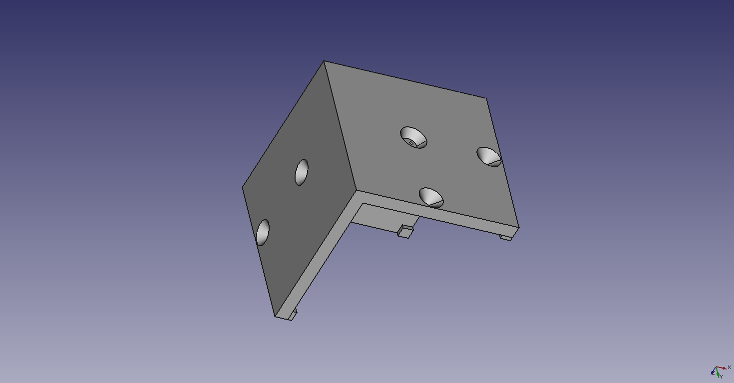
| 00:46, 20 August 2017 | Cubo.fcstd (file) | 234 KB | Corner cube. OSE developer test. | 1 | |
| 11:32, 24 August 2017 | Dev032 German Crespo.png (file) |  |
75 KB | 1 | |
| 04:15, 27 August 2017 | German.jpg (file) |  |
235 KB | Yo | 1 |
| 00:49, 22 October 2017 | MinutesEG.jpg (file) |  |
56 KB | Formatting example on YouTube comment. | 1 |
| 06:46, 7 November 2017 | Frame16Single.fcstd (file) | 16 KB | Square frame. One side. D3D 16" | 1 | |
| 06:49, 7 November 2017 | Frame16Single.pdf (file) | 172 KB | Very basic dimensional drawing. Square frame for 16" D3D printer. | 1 | |
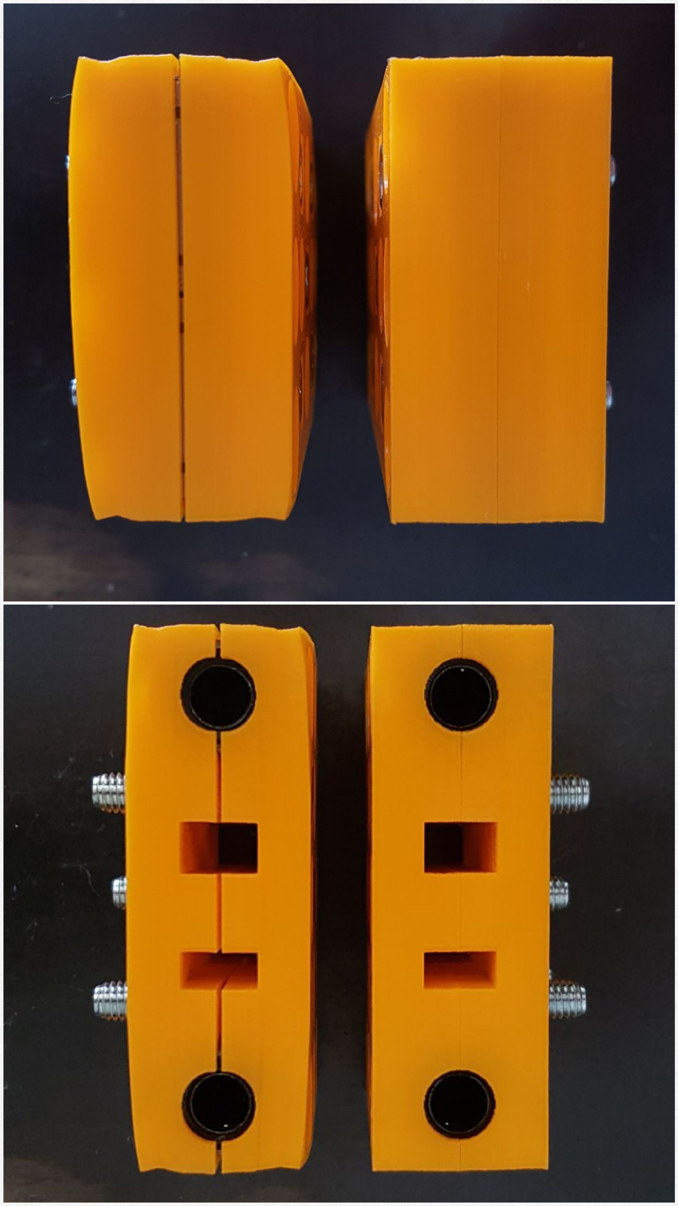
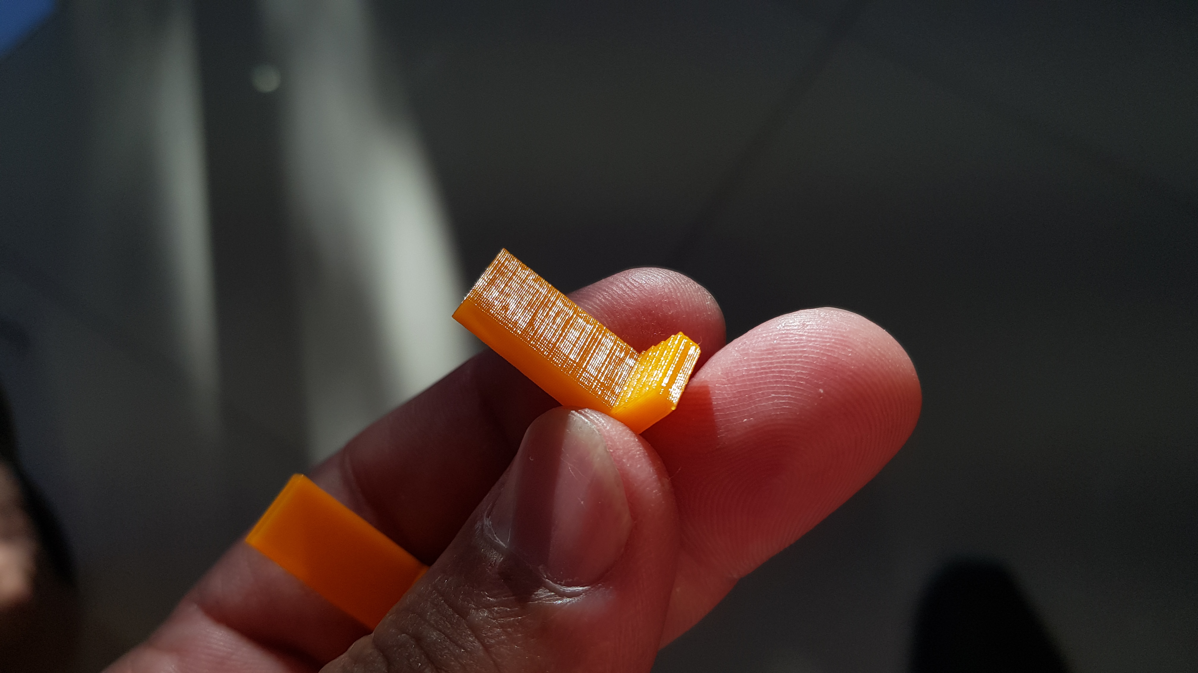
| 06:11, 20 December 2017 | Carriage before after brim.jpg (file) |  |
330 KB | Two Carriage Side printed with different settings. Note warping in the first attempt. Linear bearings are misaligned and the flat area on the outer surfaces. The second attempt was printed using less material for shell and filling. HBP temperature was... | 1 |
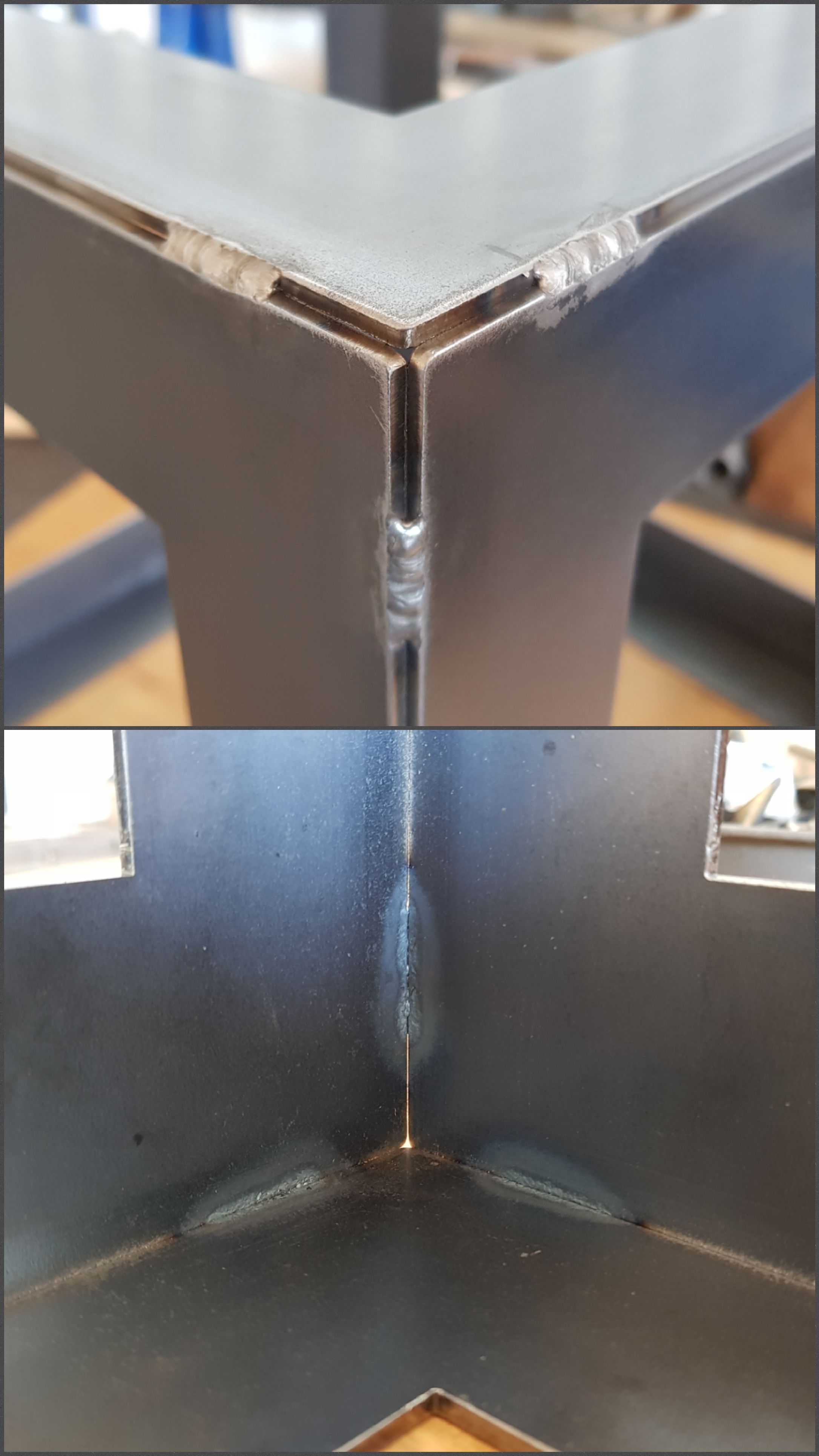
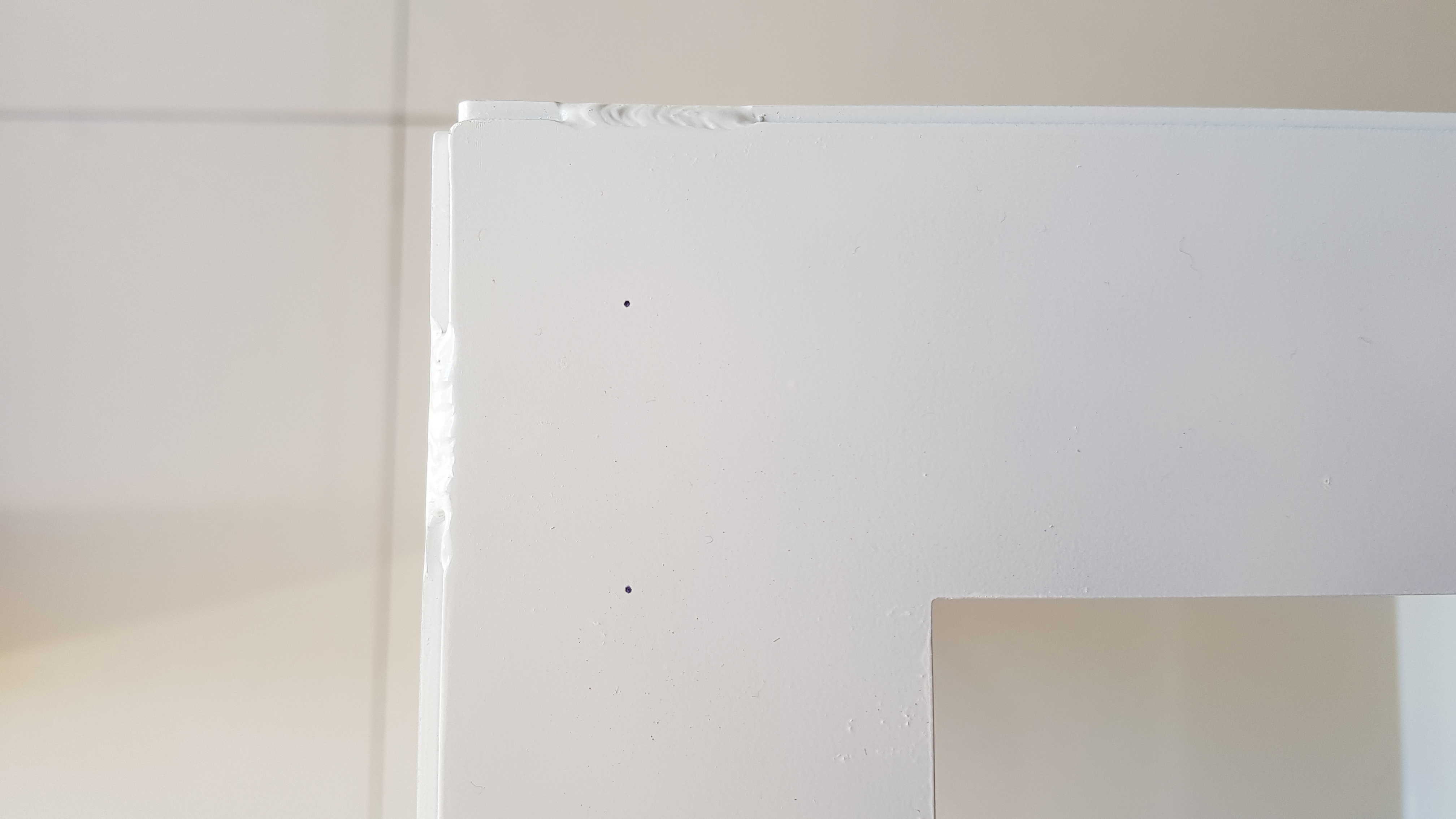
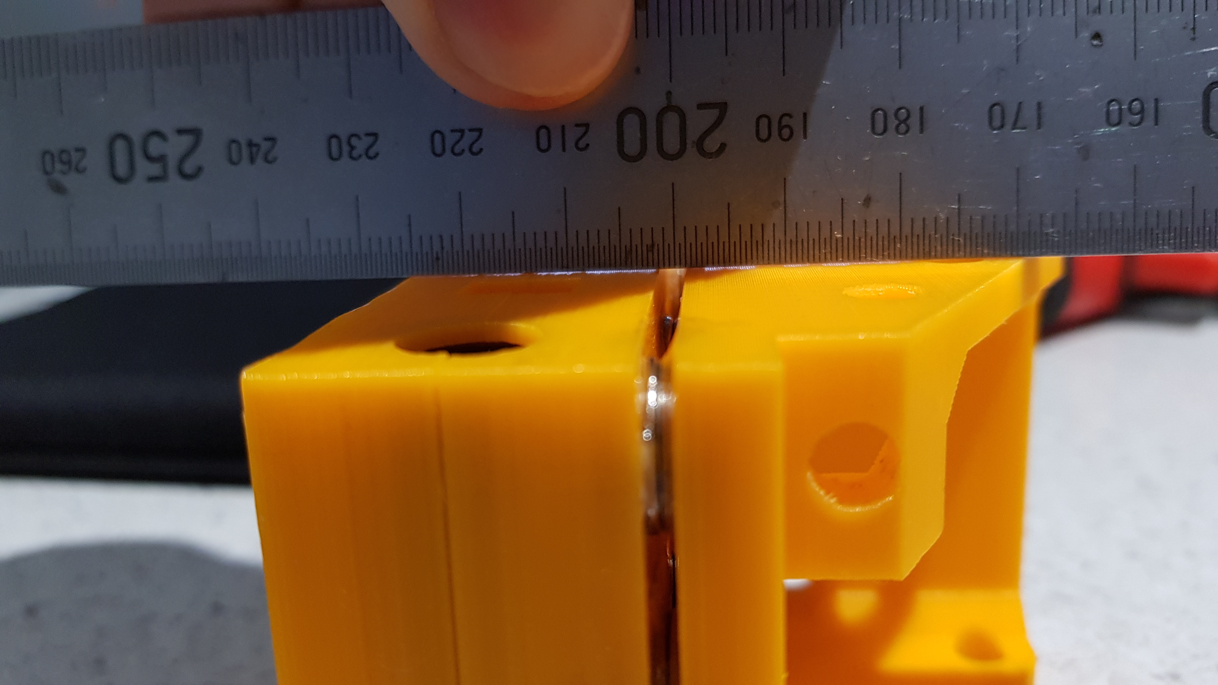
| 06:41, 20 December 2017 | Outside inside corner.jpg (file) |  |
403 KB | Outside and inside view ao a stitch welded corner of the frame. | 1 |
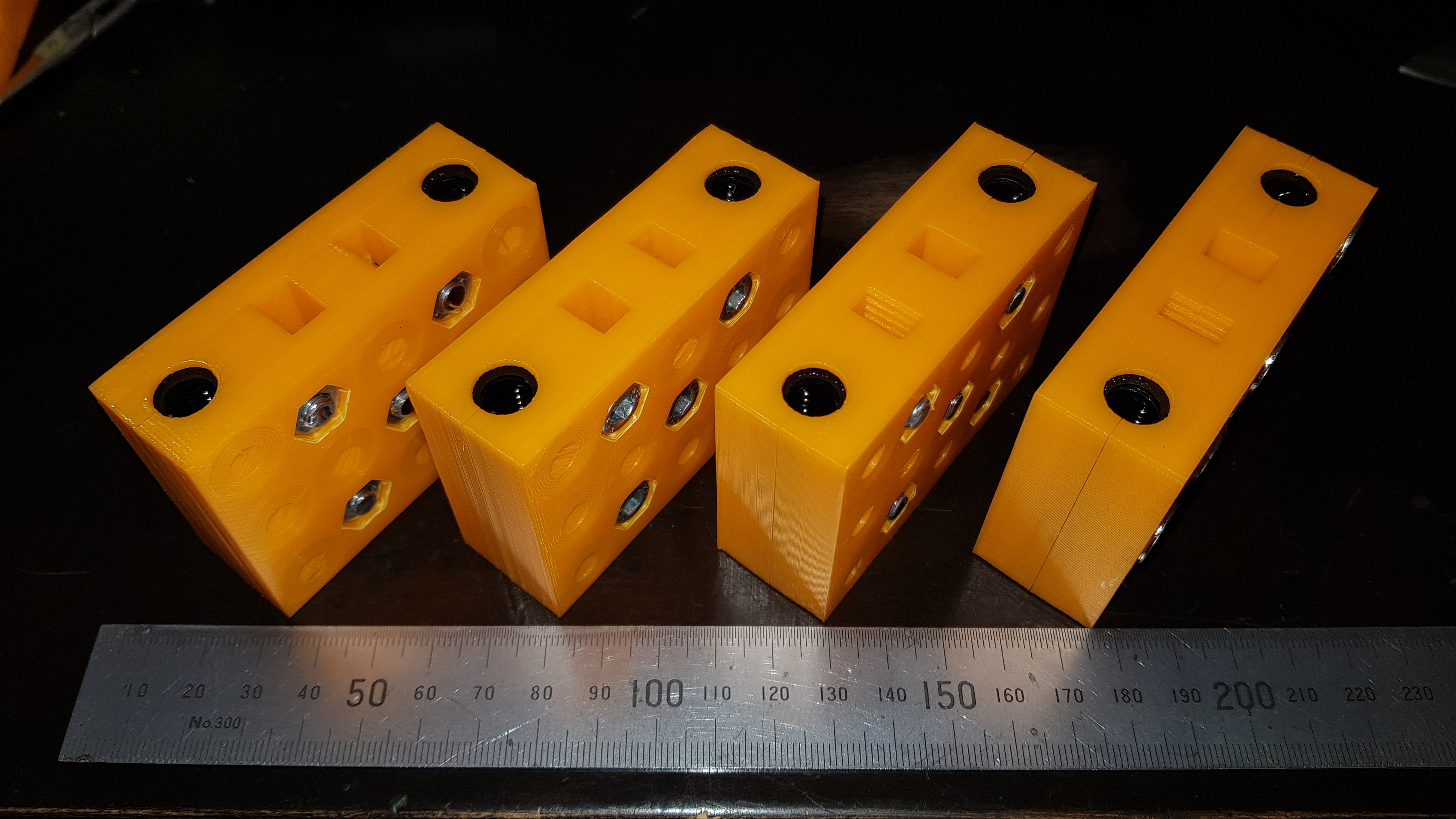
| 11:50, 23 December 2017 | Four carriages.jpg (file) |  |
2.69 MB | Four assembled carriages. | 1 |
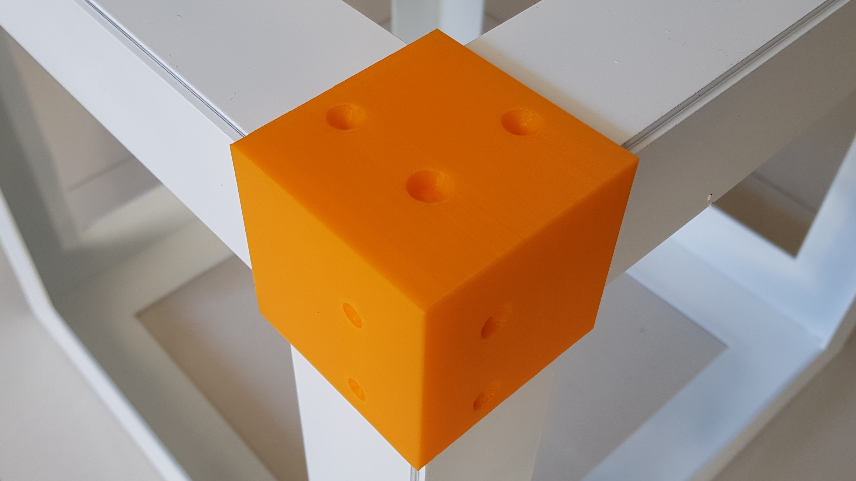
| 11:59, 23 December 2017 | Holes template02.jpg (file) |  |
506 KB | Template to place holes on the D3D frame's corners. | 1 |
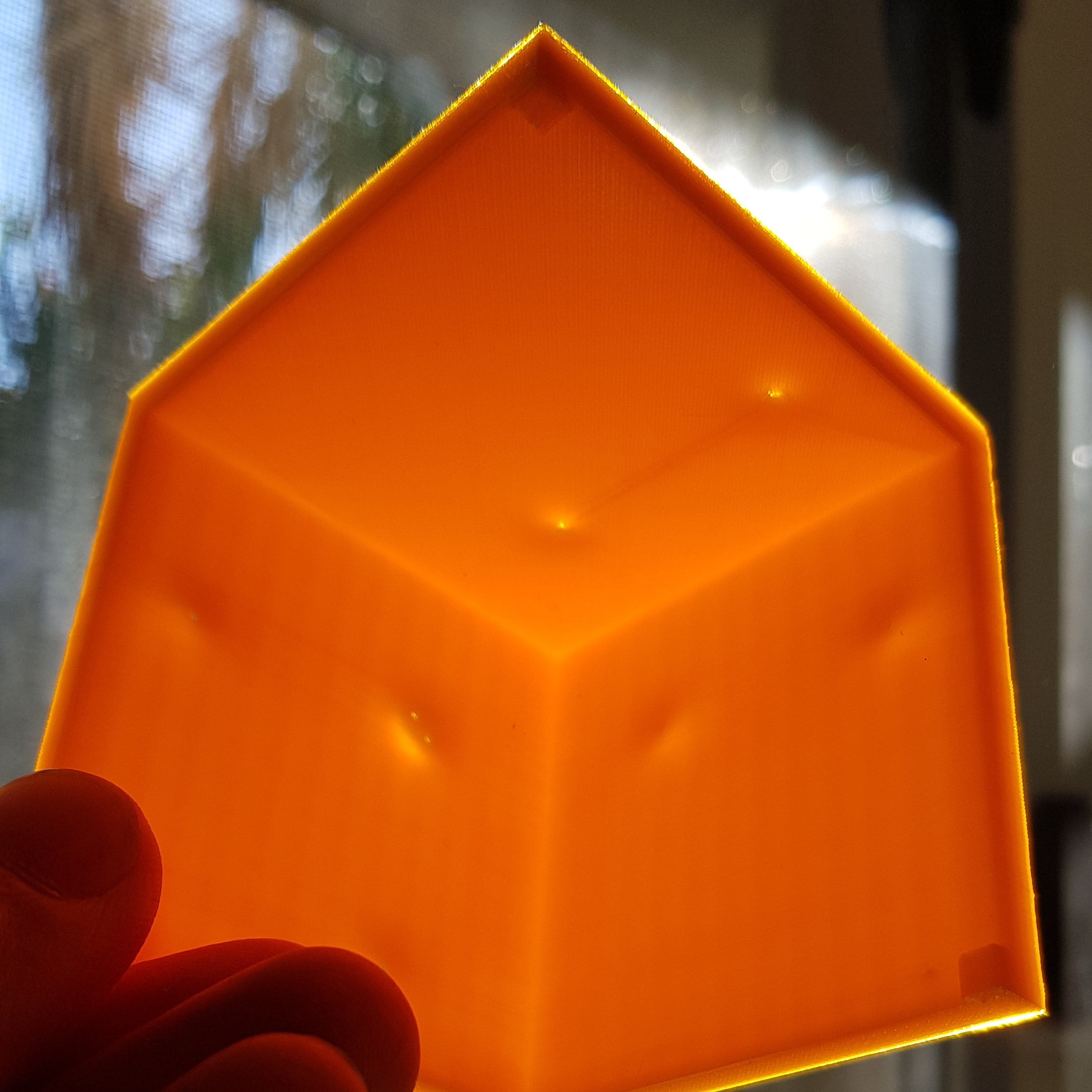
| 12:00, 23 December 2017 | Holes template01.jpg (file) |  |
672 KB | Template to place holes on the D3D frame's corners. | 1 |
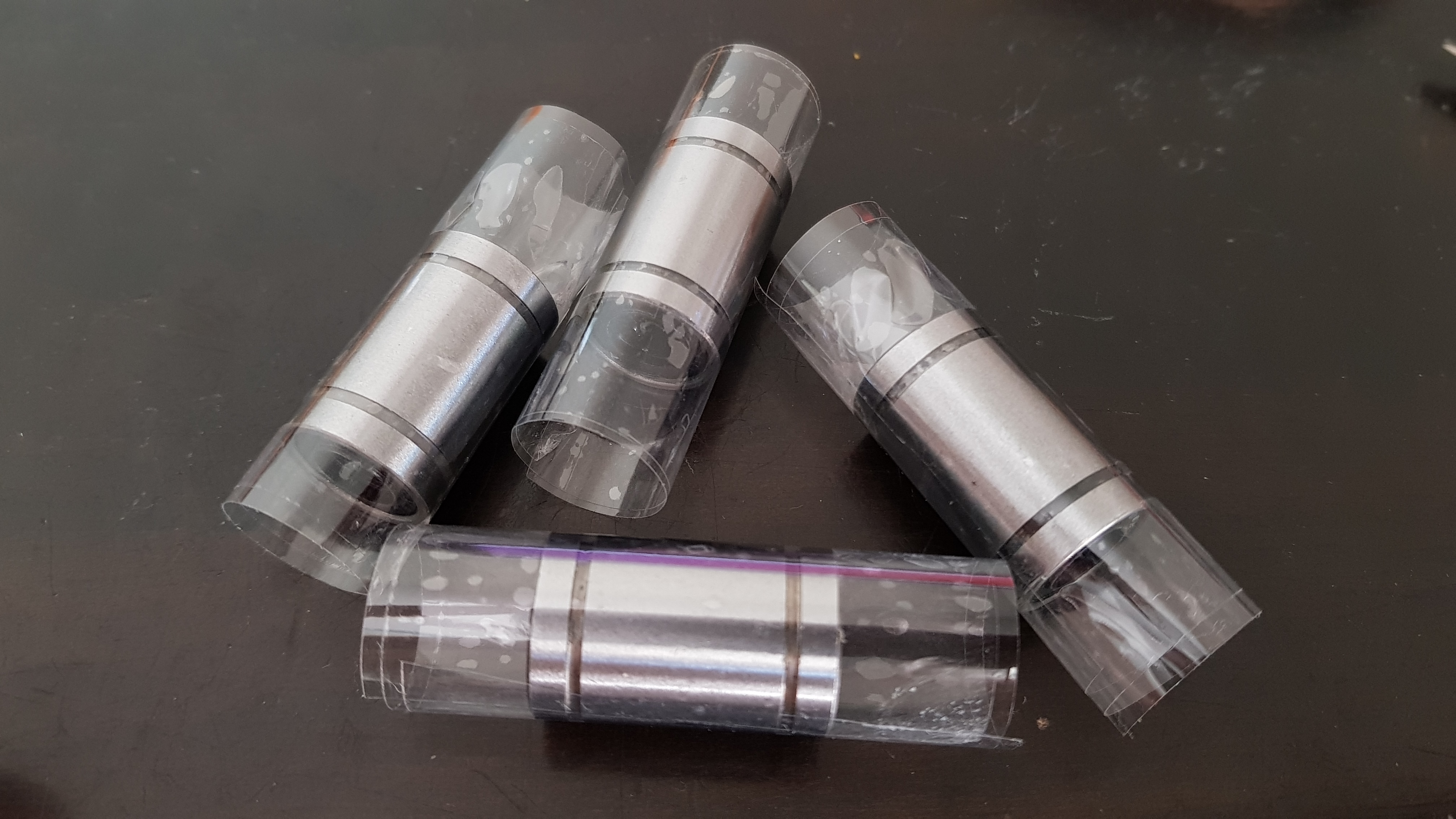
| 12:14, 23 December 2017 | Linear bearing tape.jpg (file) |  |
2.48 MB | Linear bearings with increased diameter. | 1 |
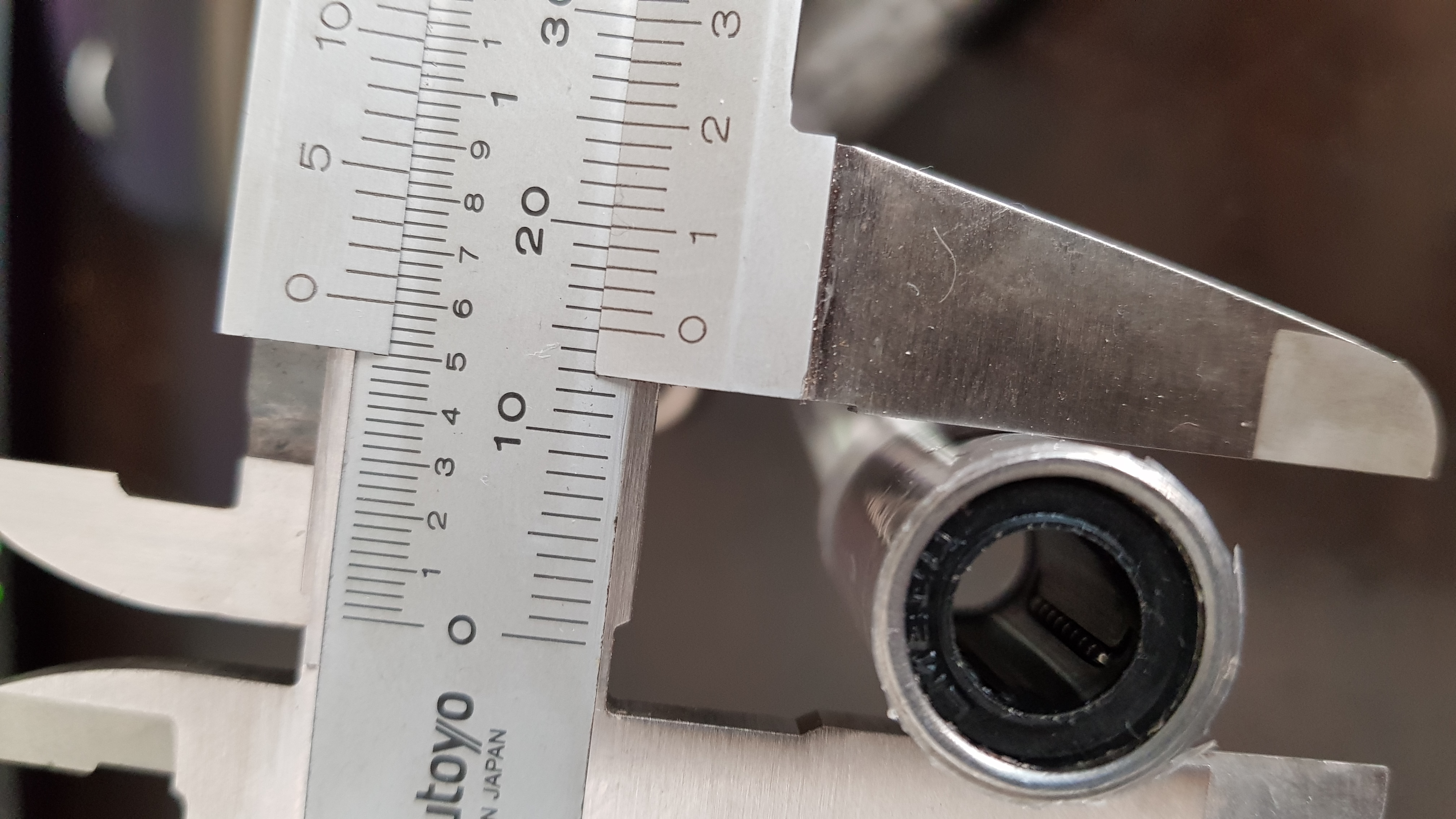
| 12:16, 23 December 2017 | Linear bearing tape00.jpg (file) |  |
2.5 MB | Measuring increased diameter on a linear bearing. | 1 |
| 11:18, 26 December 2017 | D3DAustralia Holes Template.png (file) |  |
21 KB | Template to accurately place guide marks for the holes where the Y axes mount to the frame of the printer. | 1 |
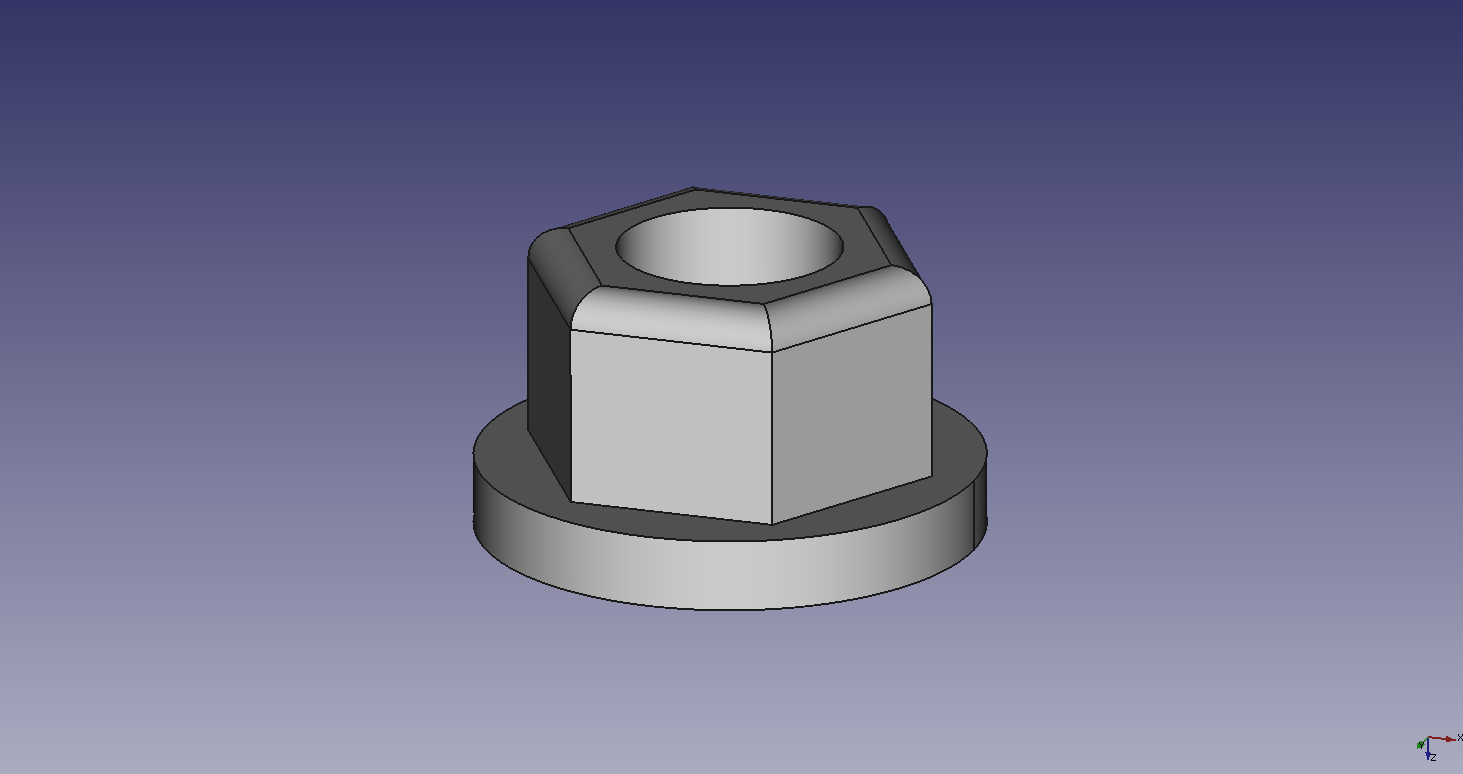
| 11:25, 26 December 2017 | D3DAustralia Axes Spacer.png (file) | 20 KB | Spacers that allow for a 2mm separation between D3D frame and all axes assemblies when affixed with bolts. | 1 | |
| 05:18, 27 December 2017 | Aus hole marks.jpg (file) |  |
1.79 MB | Markings placed with template tool. D3D Australia | 1 |
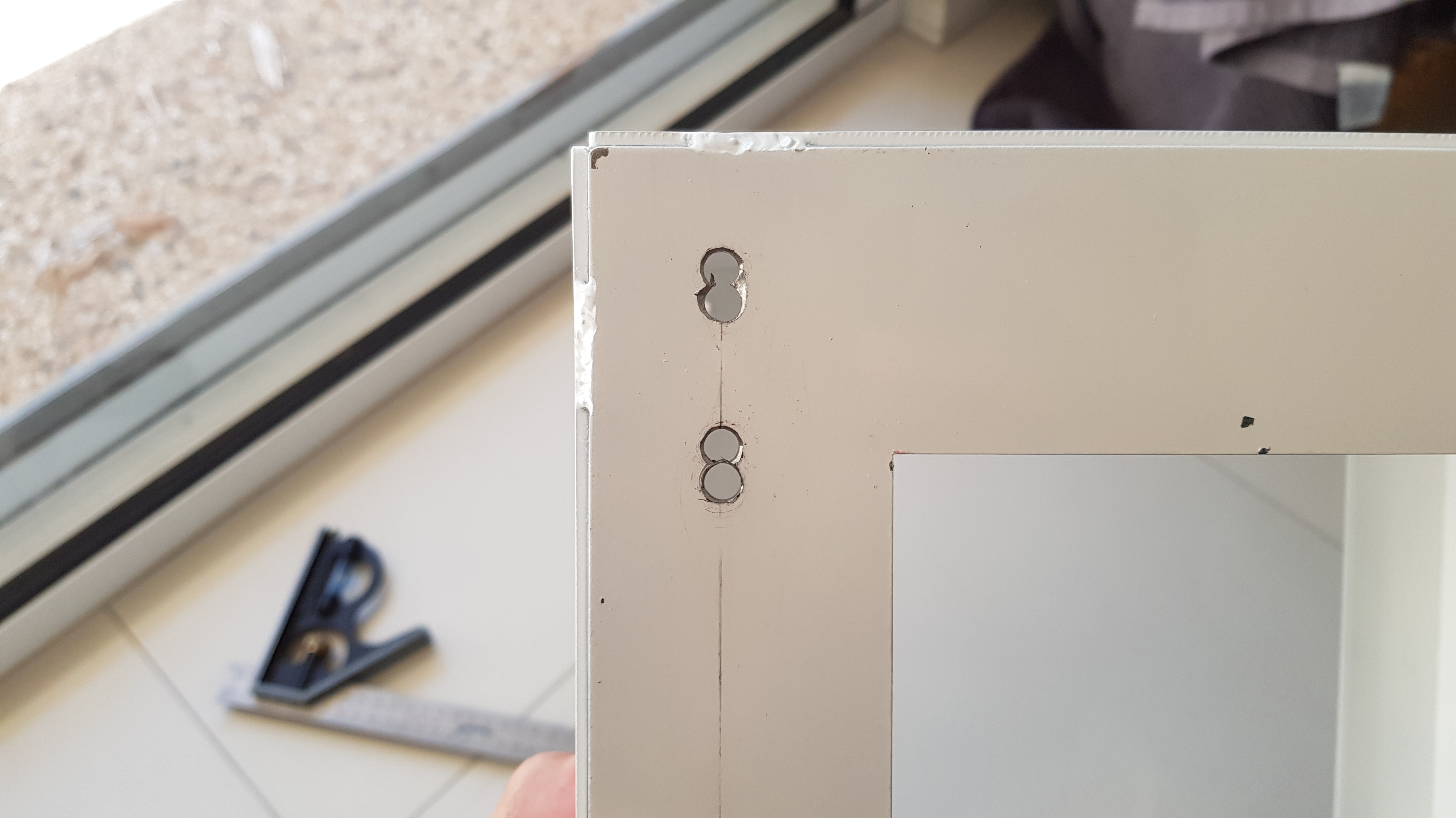
| 05:21, 27 December 2017 | Aus holes misplaced.jpg (file) |  |
2.1 MB | Redrilled holes. Displaced 6mm to be able to drill next to the first set. | 1 |
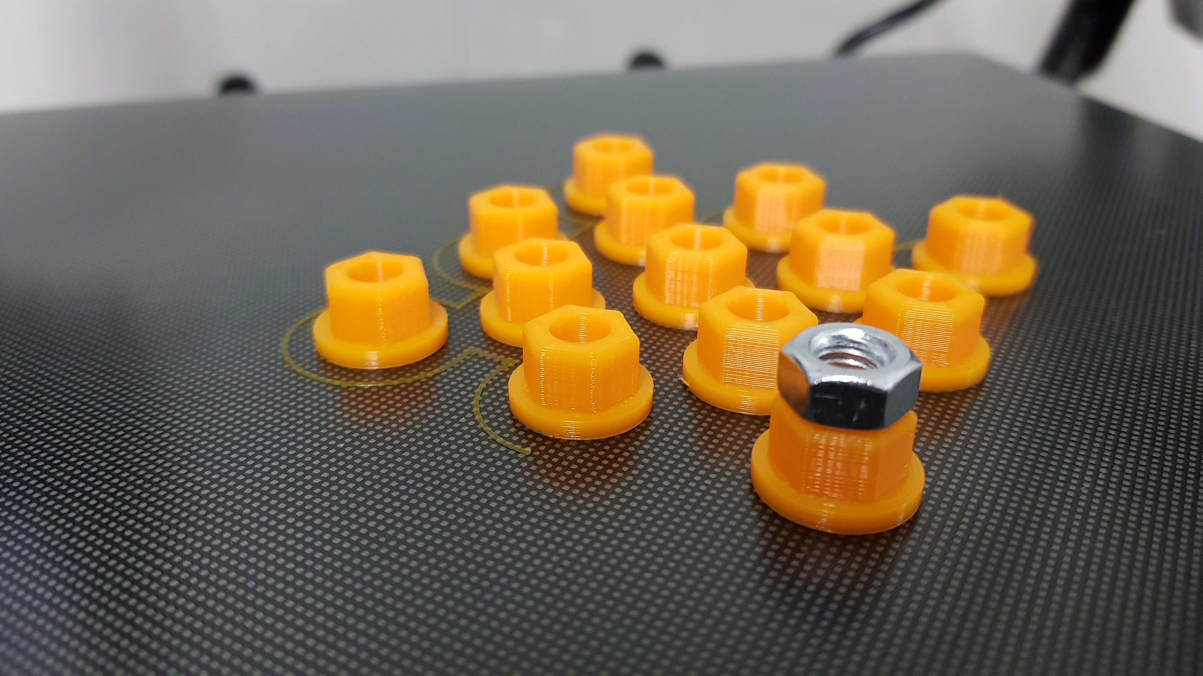
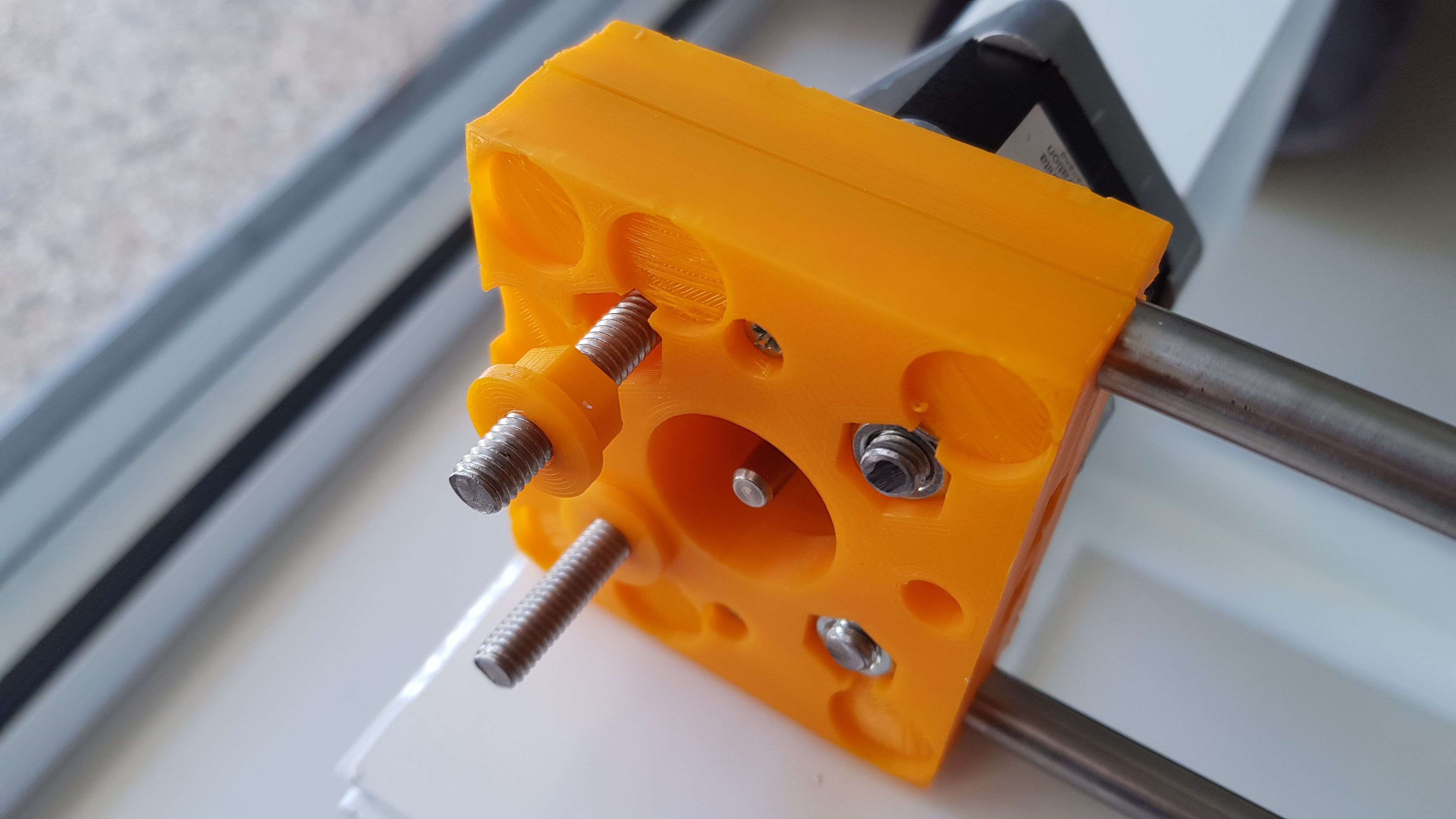
| 05:23, 27 December 2017 | Aus spacers.jpg (file) | 2.89 MB | Spacers to mount axes using the bolts that squeeze the end sandwiches (motor and idler) together. | 1 | |
| 05:26, 27 December 2017 | Aus spacer motor.jpg (file) | 2.06 MB | Detail of the spacers on the motor side. | 1 | |
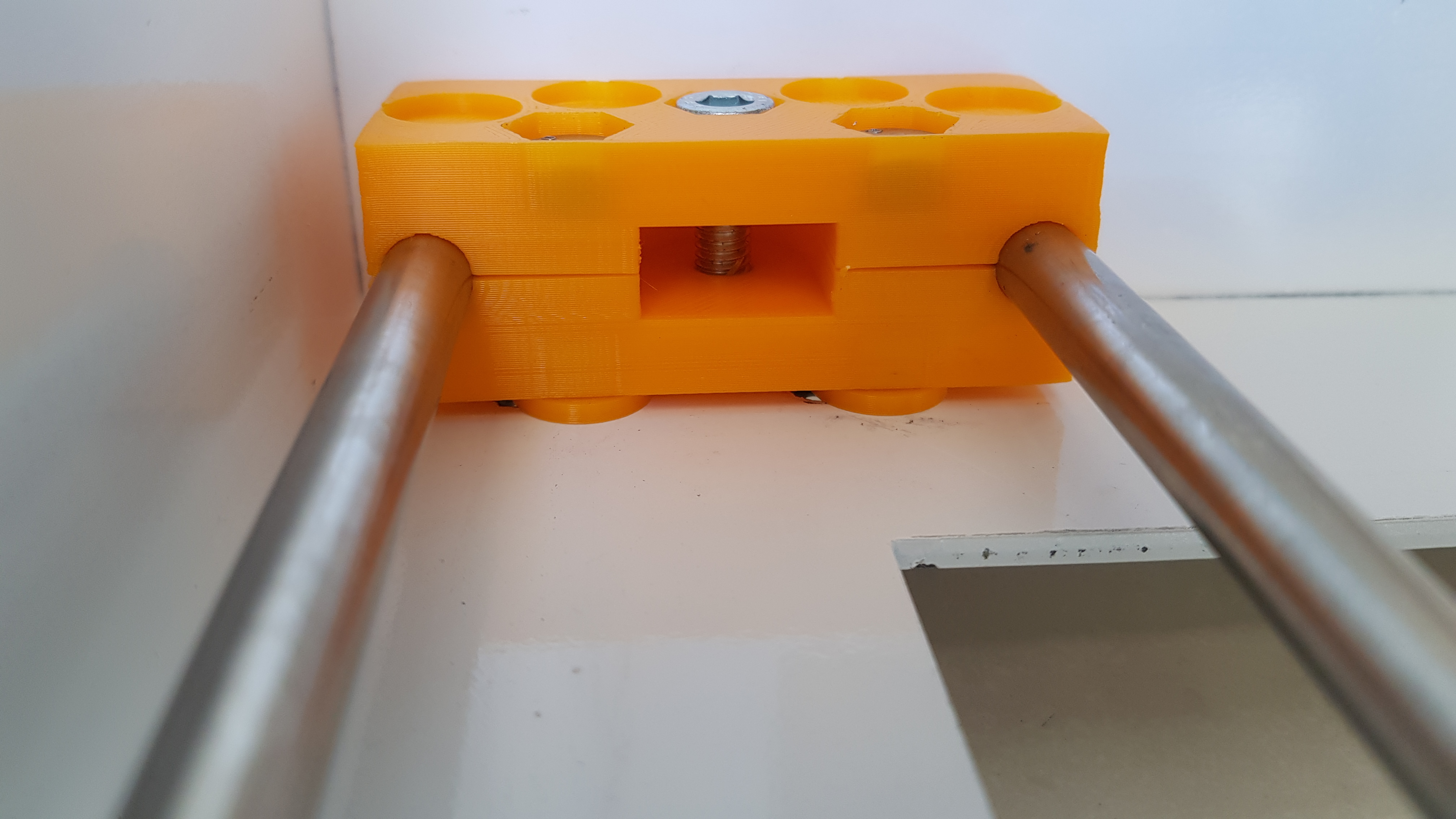
| 05:27, 27 December 2017 | Aus spacer idler.jpg (file) | 2.07 MB | Detail of the spacers on the idler side. | 1 | |
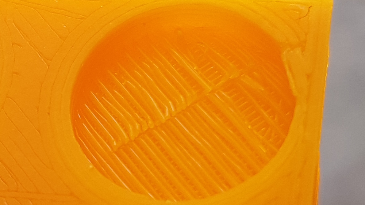
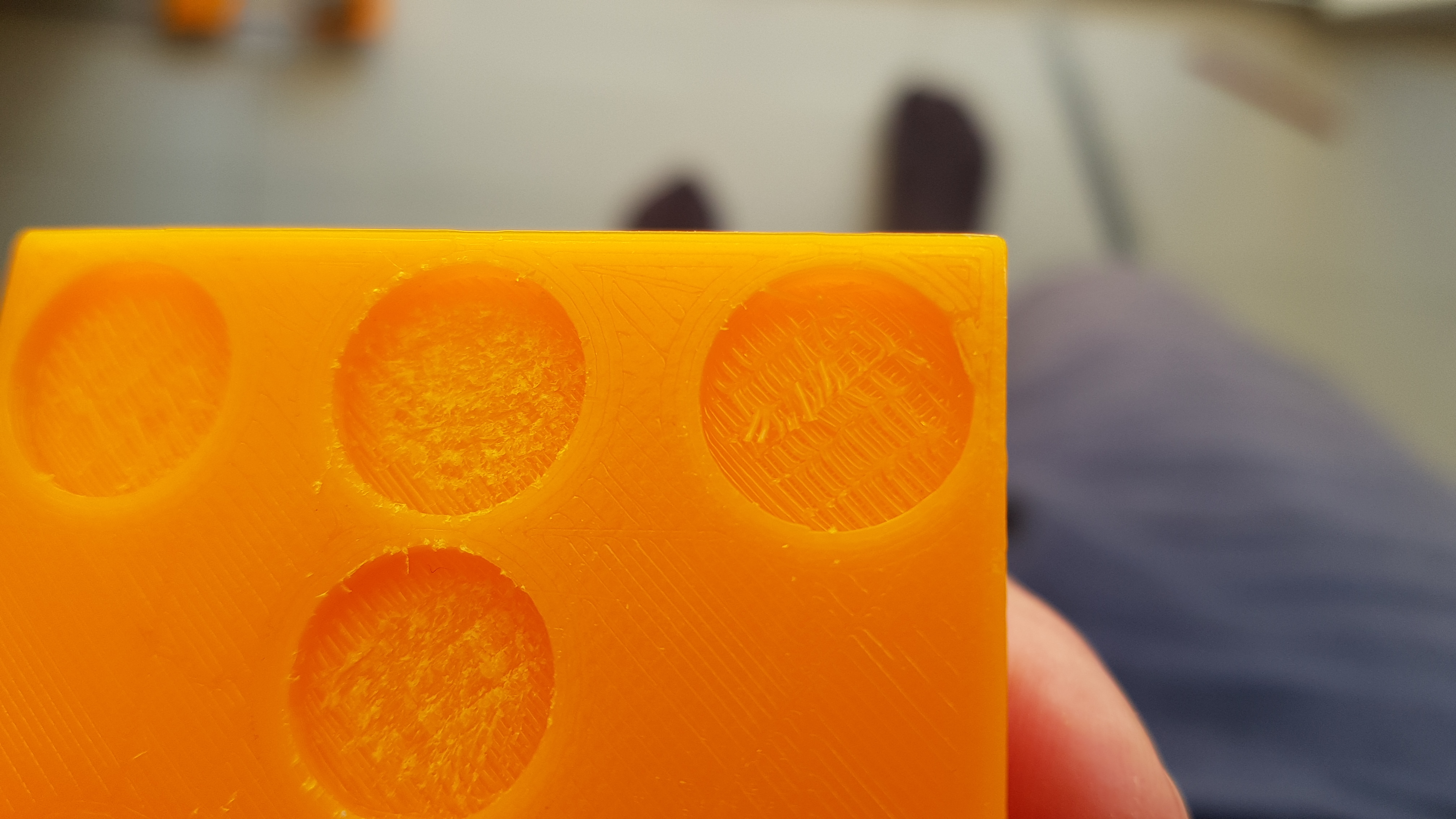
| 21:50, 30 December 2017 | Bridging filaments.jpg (file) |  |
410 KB | Lack of adhesion between the first layer the bottom of a magnet socket and the following layer due to the printer having to bridge the gap. | 1 |
| 21:54, 30 December 2017 | Bridging scraped.jpg (file) |  |
2.36 MB | Scraping of the loose layer in a bridged gap of the print. | 1 |
| 21:58, 30 December 2017 | Magnets taped.jpg (file) |  |
2.64 MB | Magnets being held down by tape while gluing. | 1 |
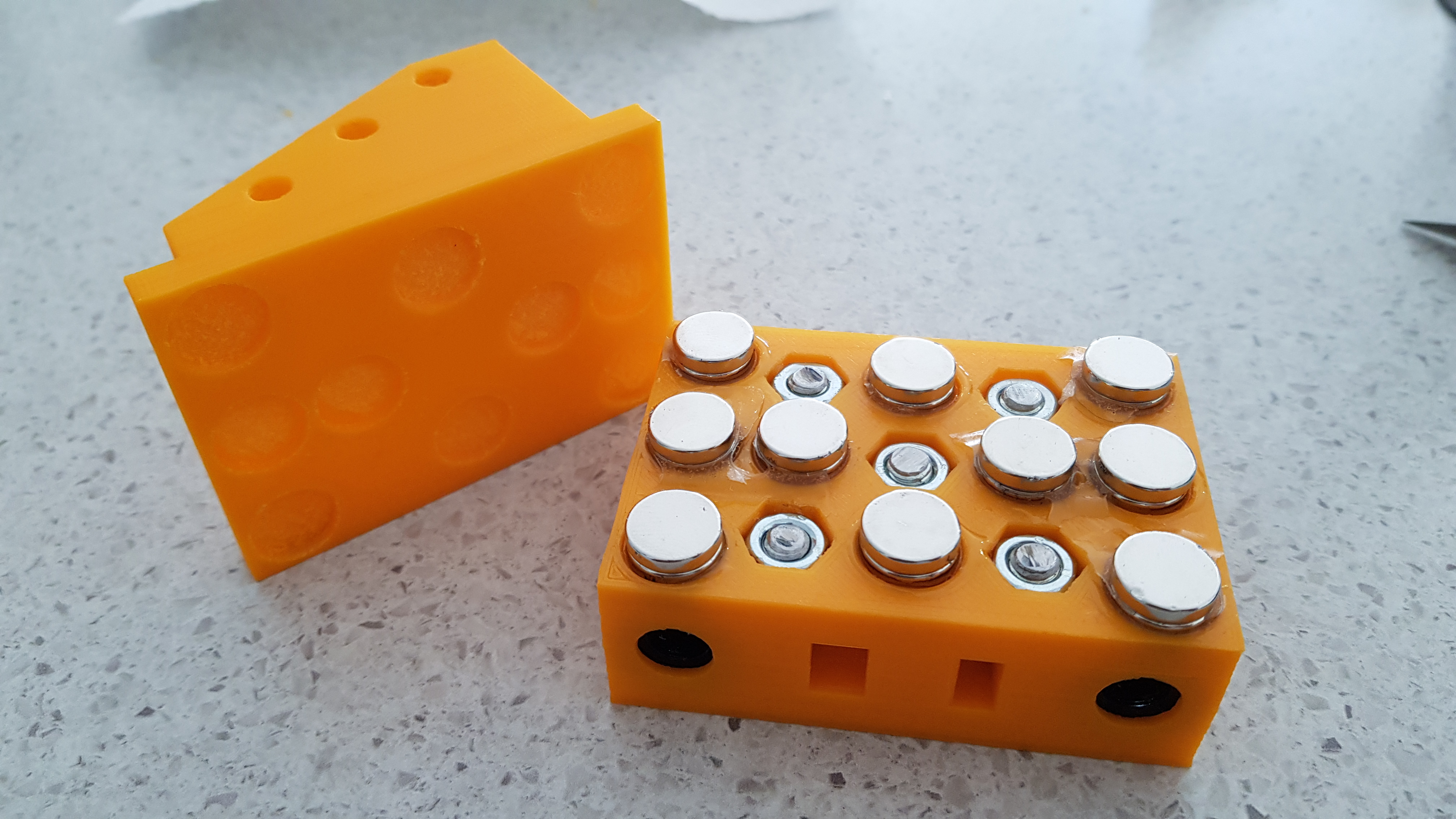
| 22:02, 30 December 2017 | Magnets extruder interface.jpg (file) |  |
2.54 MB | Sticking the magnets of the extruder interface to the carriage assembly before gluing. | 1 |
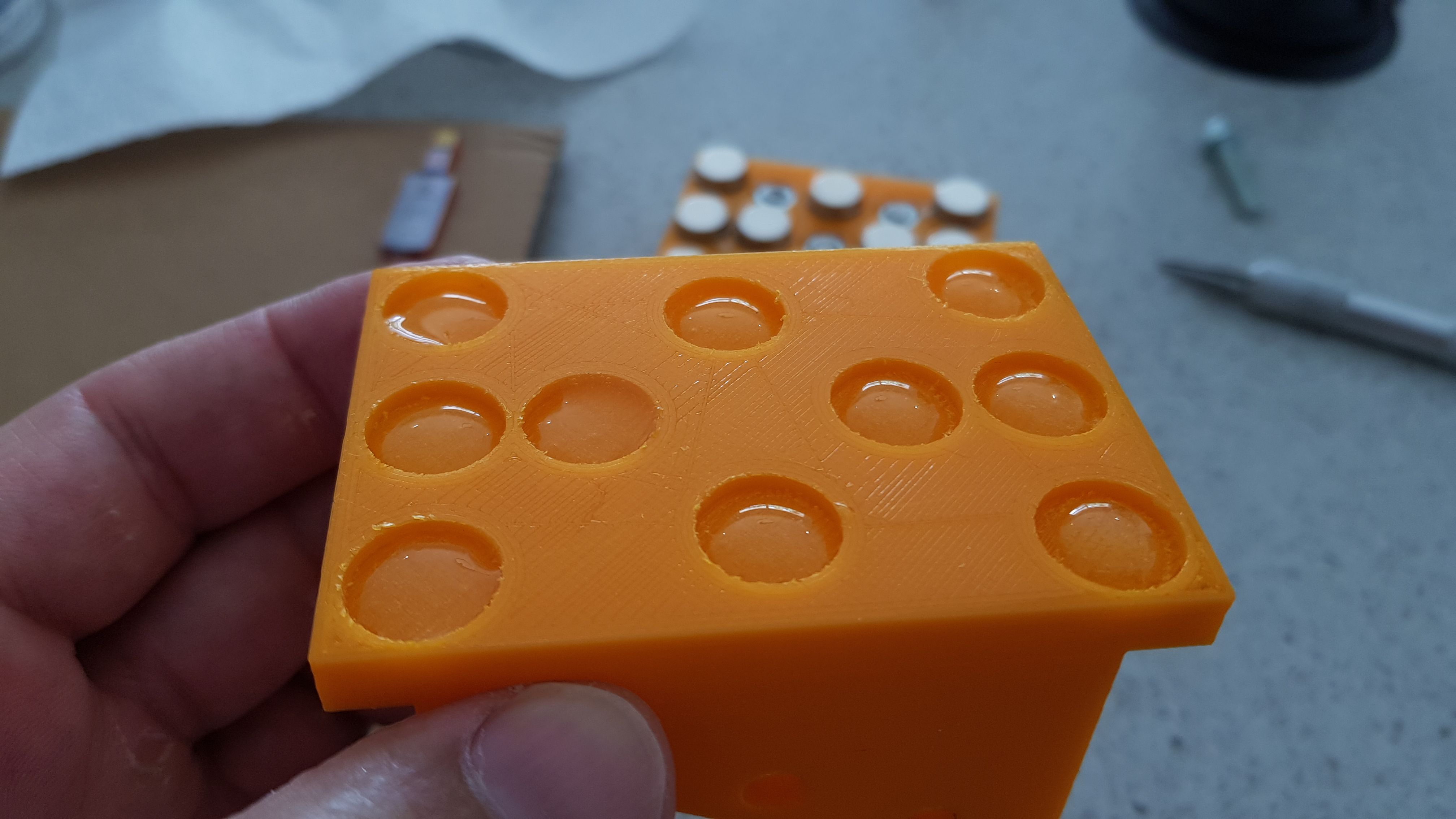
| 22:05, 30 December 2017 | Magnets epoxy.jpg (file) |  |
2.1 MB | Beads of epoxy on extruder interface. | 1 |
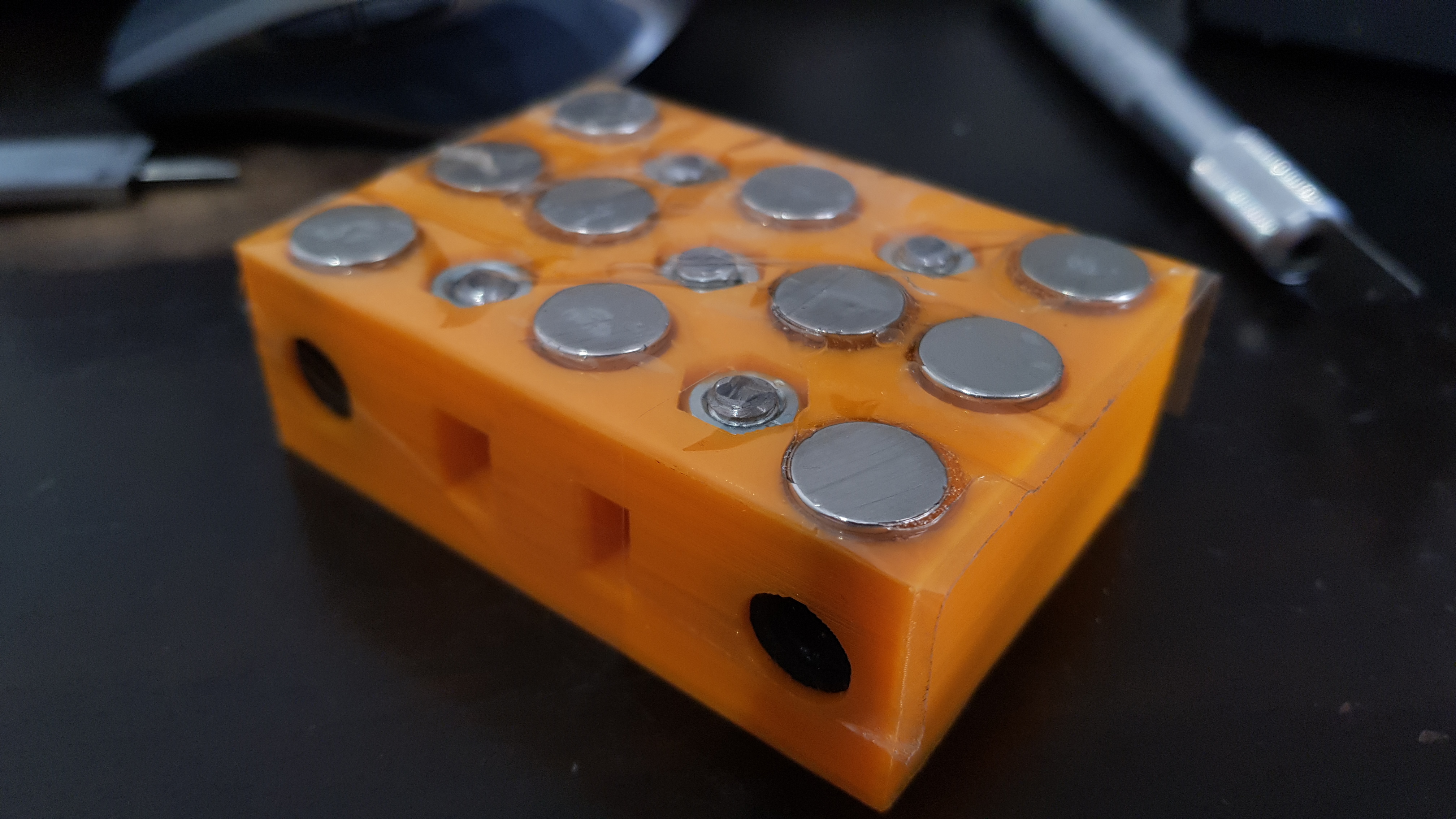
| 22:08, 30 December 2017 | Square interface carriage.jpg (file) |  |
2.75 MB | Proper alignment of parts after gluing the magnets. | 1 |
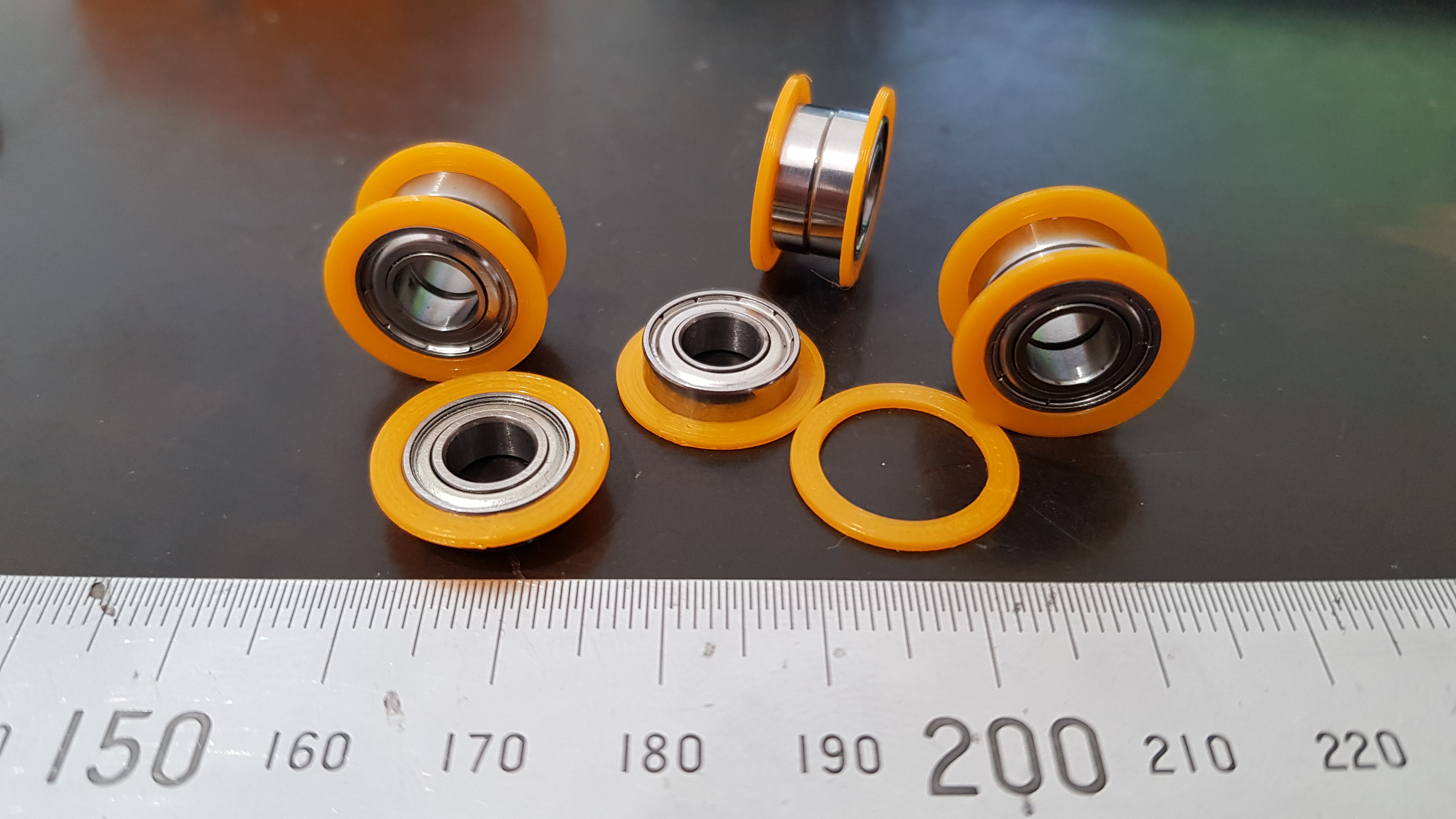
| 22:13, 30 December 2017 | Idler flanges on.jpg (file) |  |
2.82 MB | Printed flanges for idler bearings. | 1 |
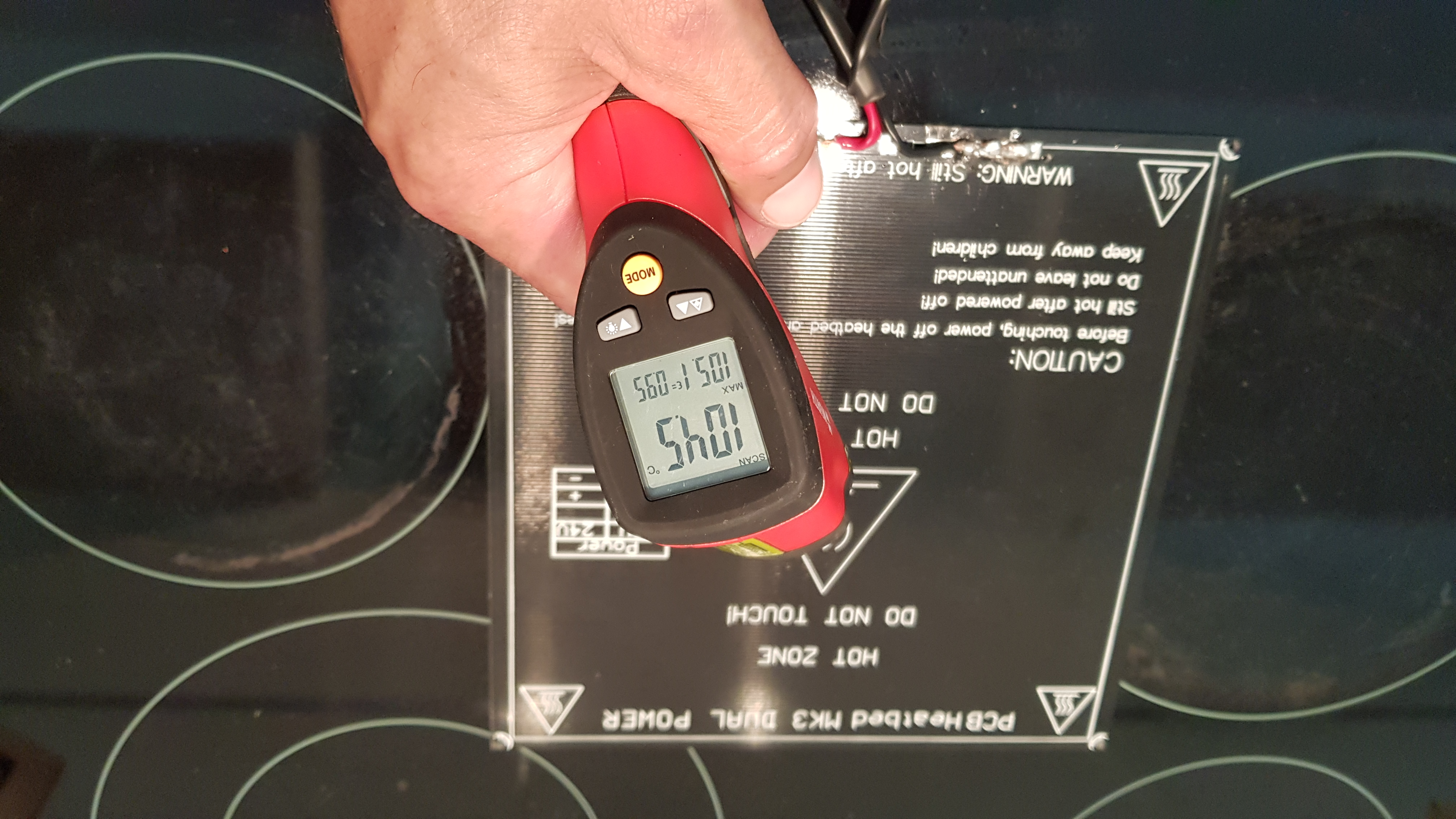
| 22:16, 30 December 2017 | HBP temp.jpg (file) |  |
3.11 MB | Maximum temperature reached by HBP without regulation. | 1 |
| 22:21, 30 December 2017 | Short idler tight.jpg (file) |  |
1.99 MB | A gap of around about 0.5mm must be seen between the two bearings | 1 |
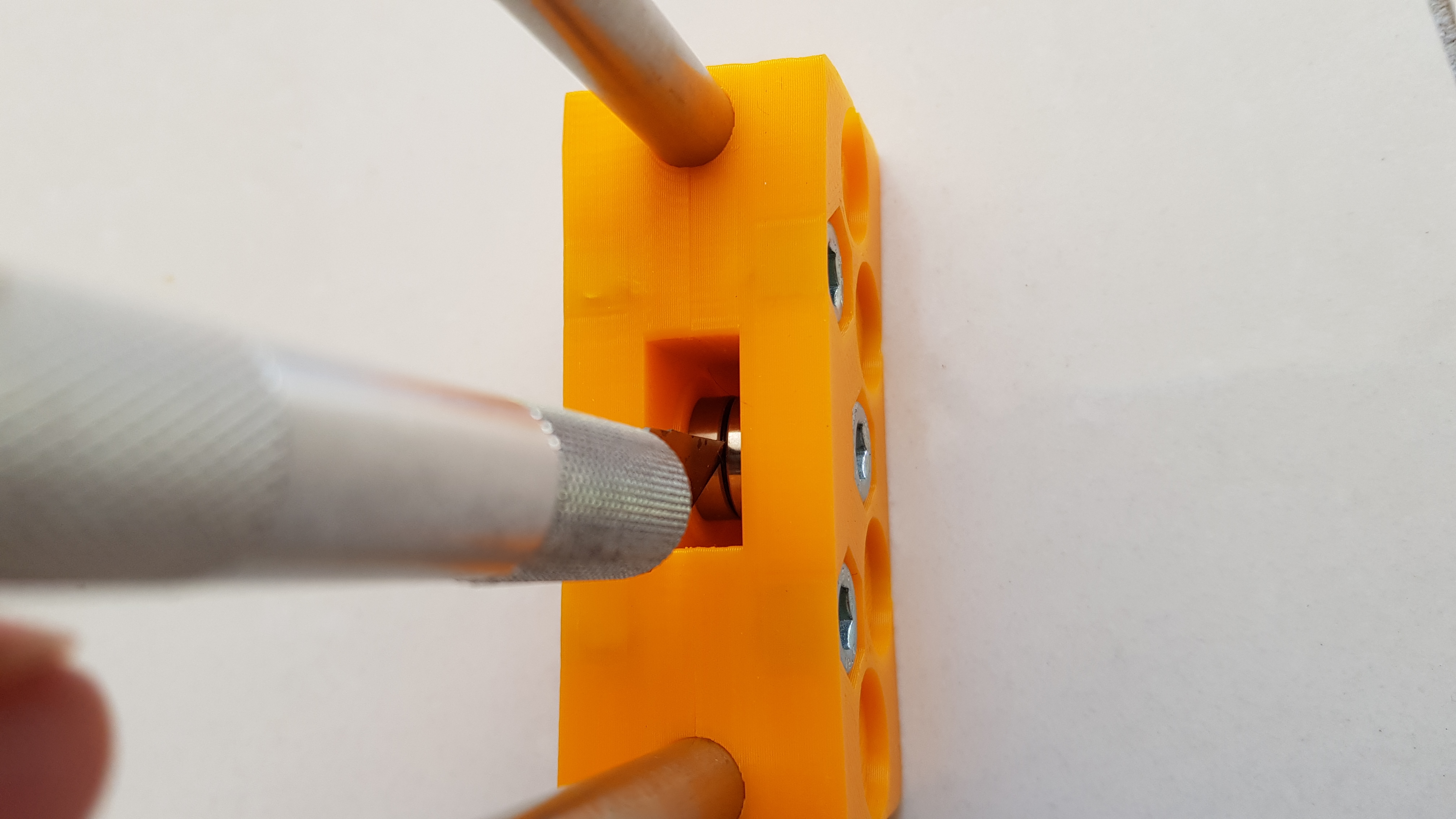
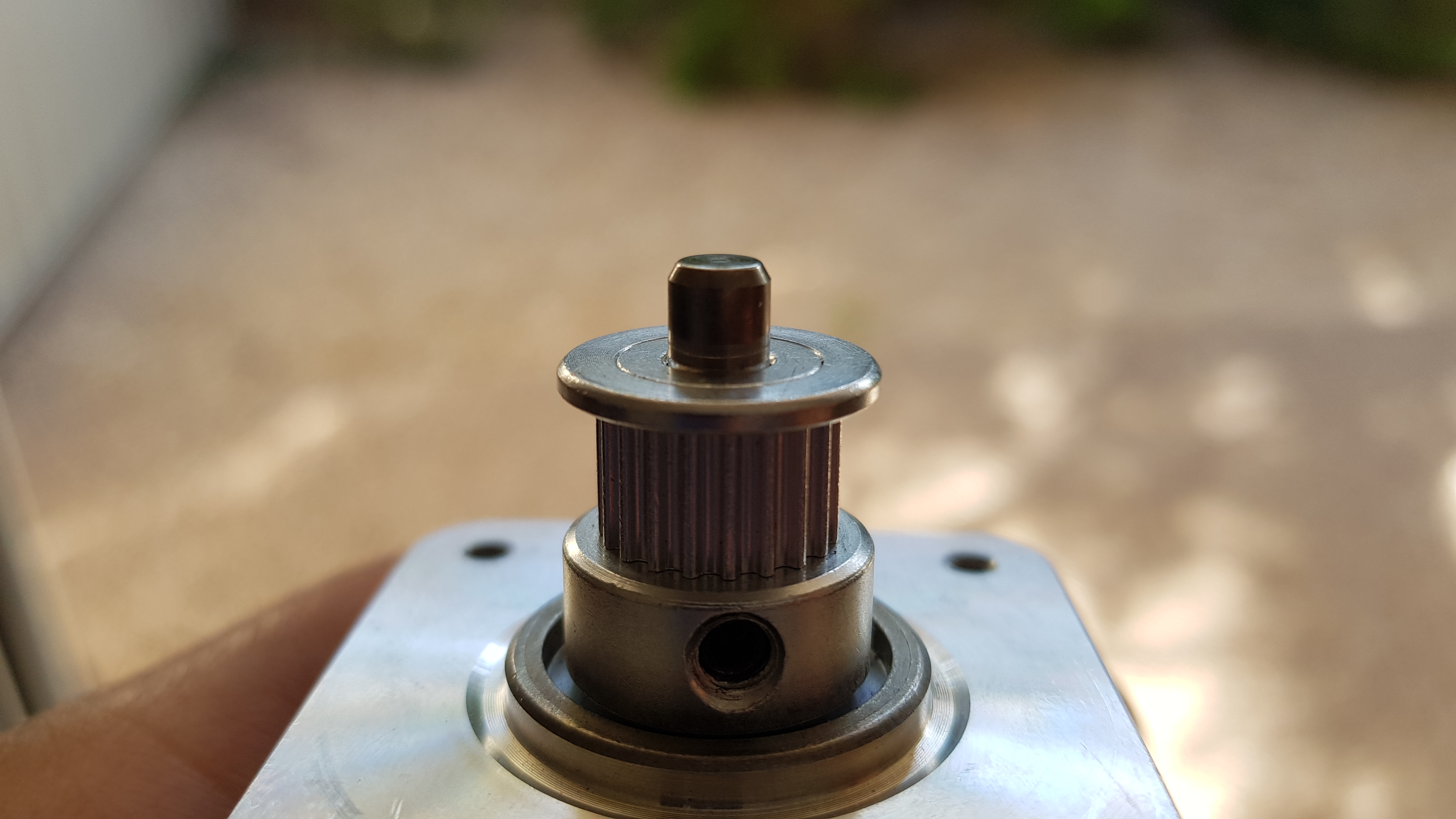
| 22:24, 30 December 2017 | Motor pulley ref.jpg (file) |  |
2.25 MB | Used a bearing as a reference to accurately place the pulleys on the motors. | 1 |
| 22:26, 30 December 2017 | Motor pulley ok.jpg (file) |  |
2.01 MB | Correct placement of pulley. | 1 |
| 22:29, 30 December 2017 | Pulley alignment.jpg (file) |  |
2.22 MB | Correct alignment. | 1 |
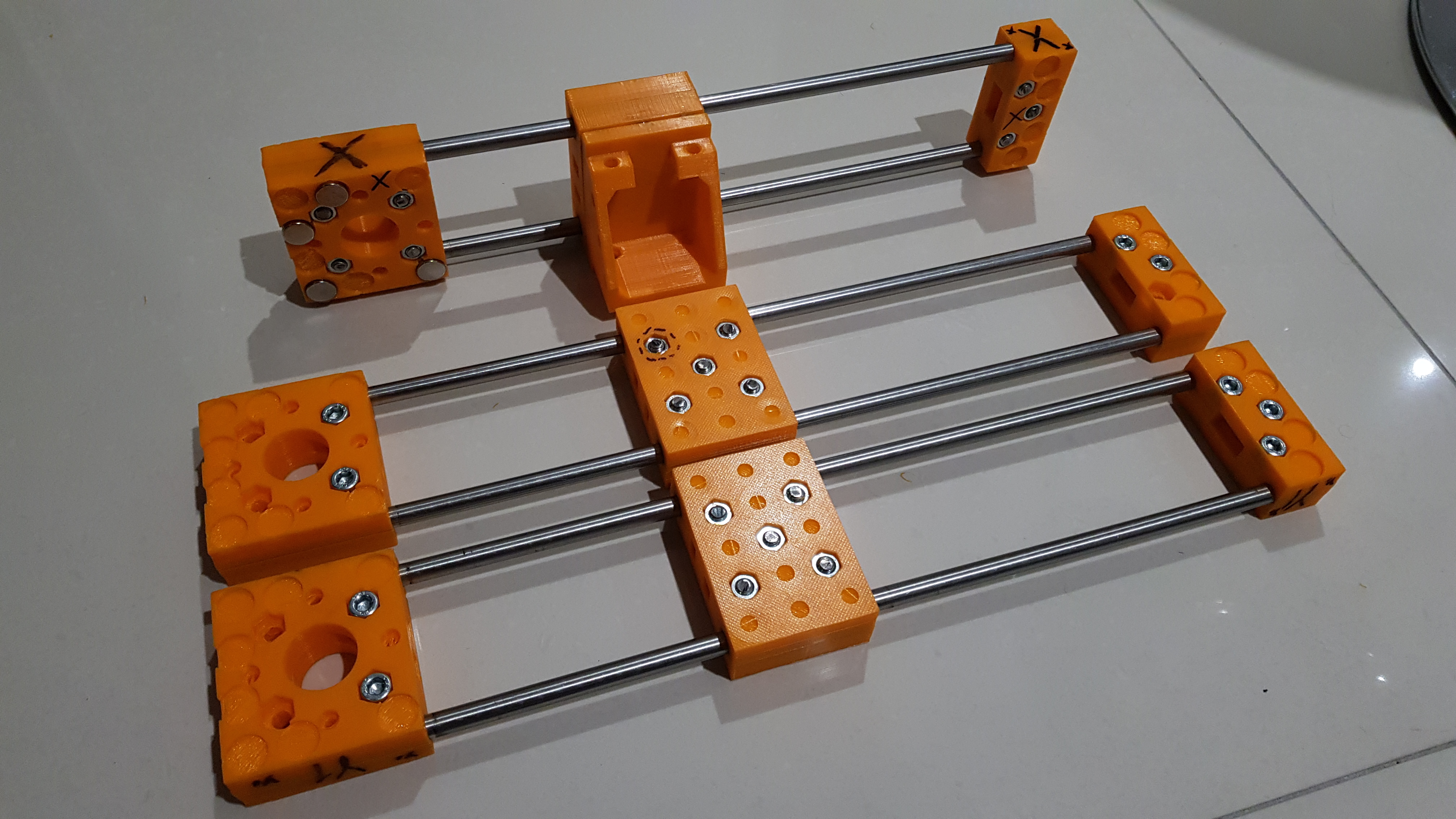
| 22:32, 30 December 2017 | X y y.jpg (file) |  |
3.04 MB | X and Y axes | 1 |
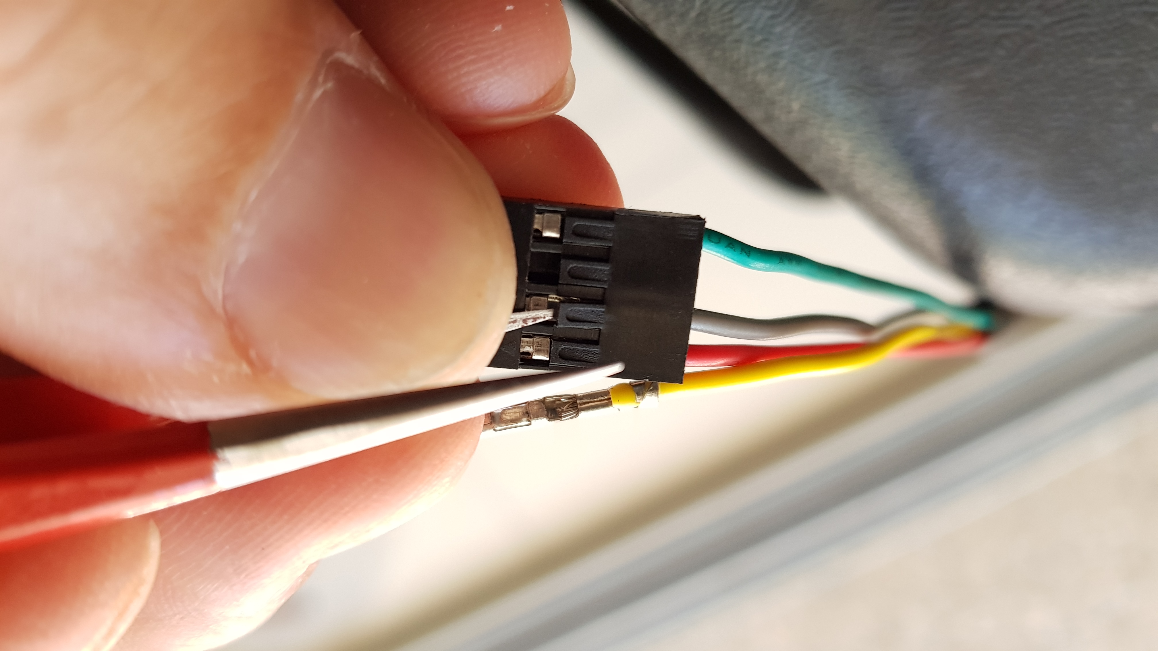
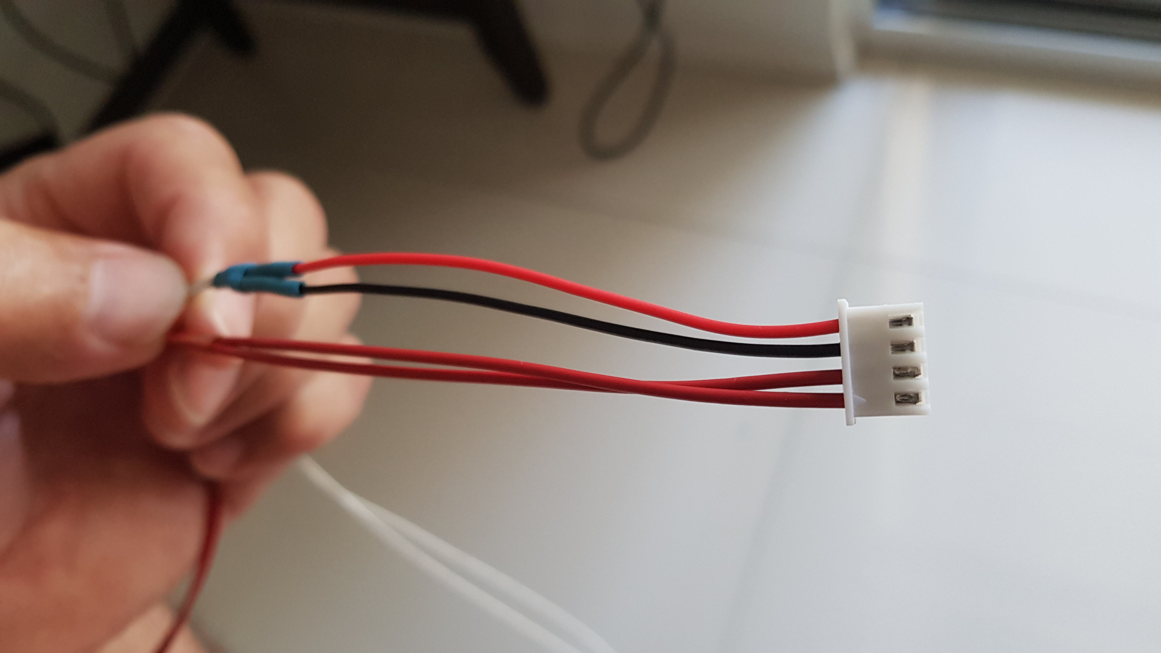
| 09:05, 1 January 2018 | Sequence dupont.jpg (file) |  |
1.77 MB | Changing wire sequence in Dupont connector. | 1 |
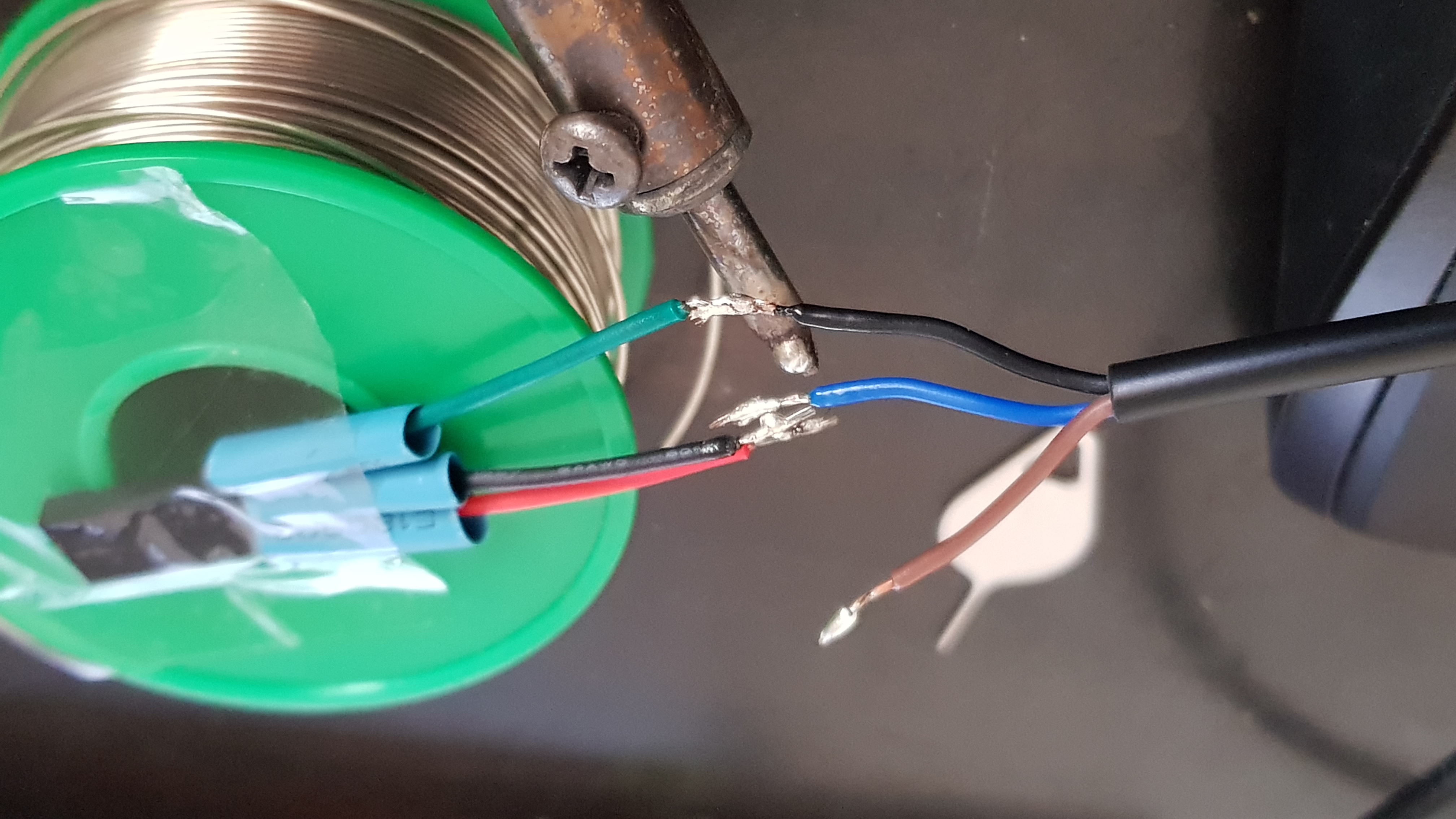
| 09:08, 1 January 2018 | Inducive sensor dupont.jpg (file) |  |
1.77 MB | Setting up wires to solder Dupont connector end to inductive sensor wiring. | 1 |
| 09:11, 1 January 2018 | Soldering inductive sensor.jpg (file) |  |
1.98 MB | Soldering inductive sensor's wires to Dupont end in the correct sequence. | 1 |
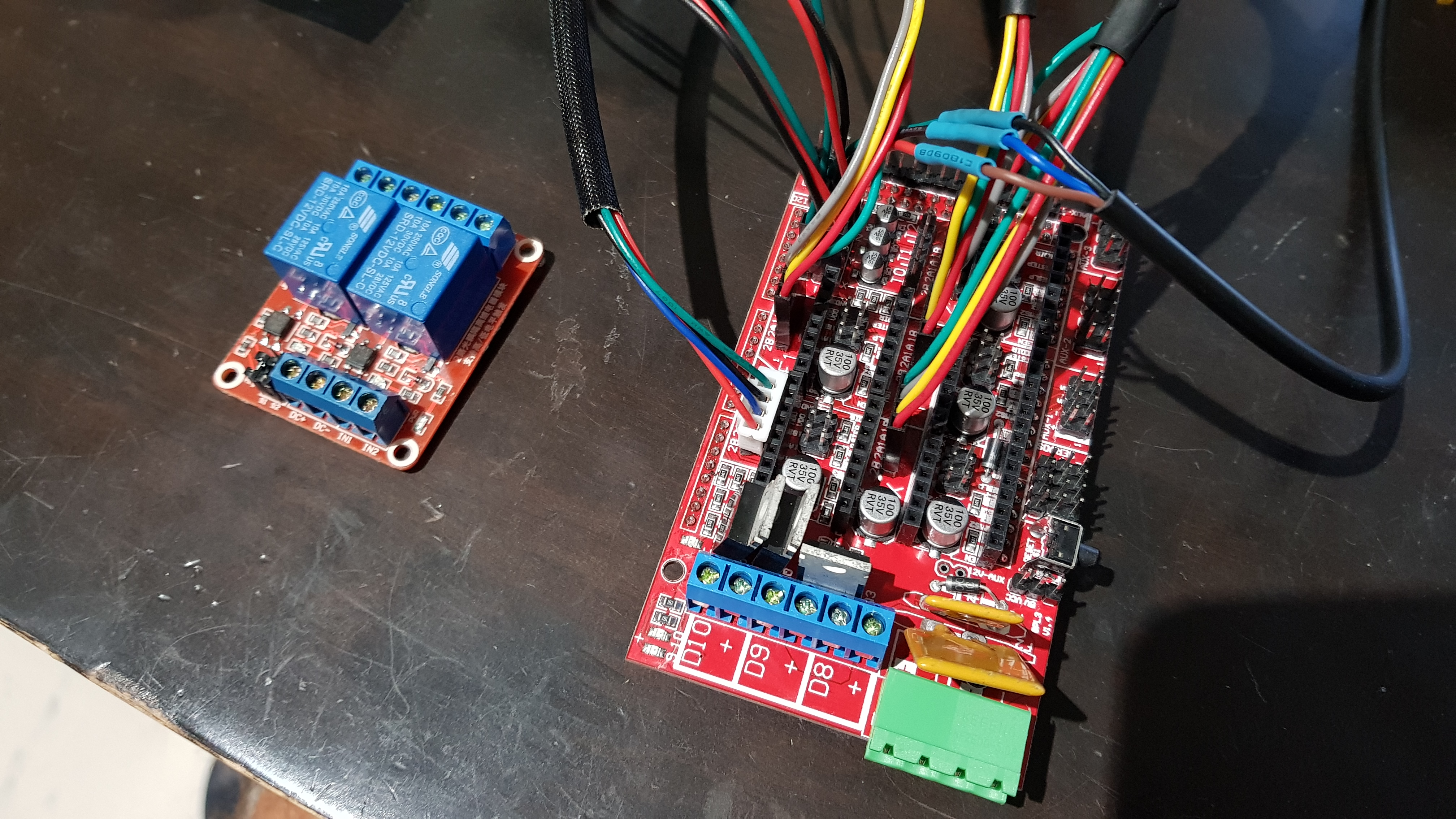
| 09:13, 1 January 2018 | Controller wiring.jpg (file) |  |
3.27 MB | Some of the wires to the controller. | 1 |
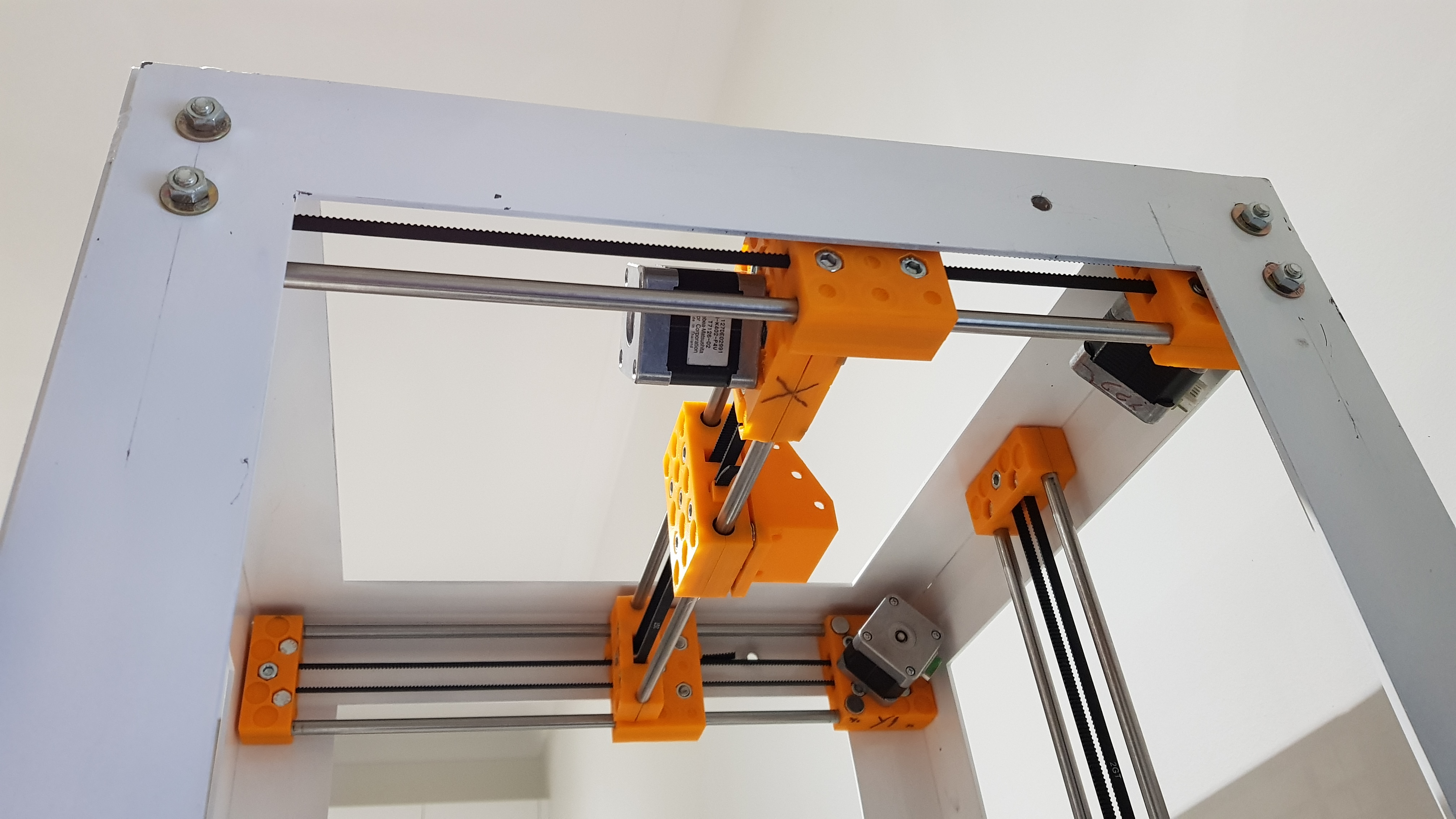
| 11:15, 3 January 2018 | All axes frame.jpg (file) |  |
15.74 MB | The disposition of all axes on the metal frame. | 1 |
| 05:10, 6 January 2018 | M6x30-2.jpg (file) |  |
2.49 MB | Trimmed off 2mm from M6x30mm SS screws. | 1 |
| 05:12, 6 January 2018 | One peg.jpg (file) |  |
2.51 MB | Belt-tightening peg | 1 |
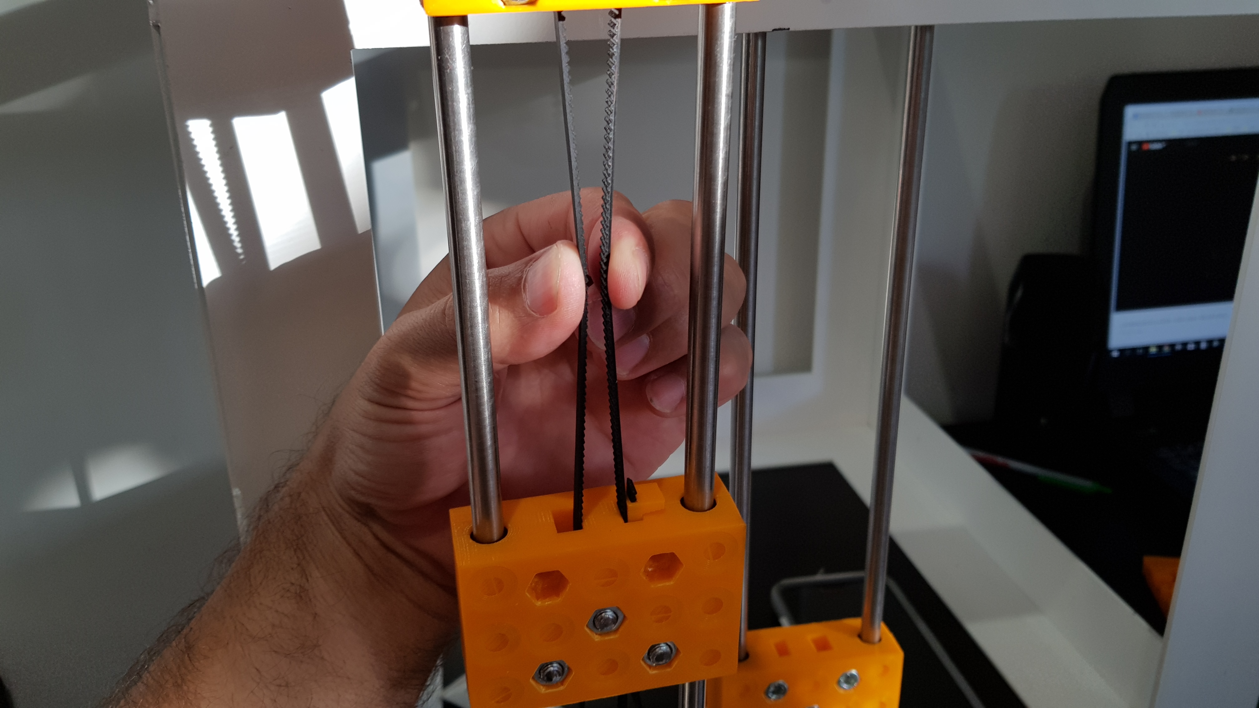
| 05:15, 6 January 2018 | Belt tension.jpg (file) |  |
2.15 MB | Tensioning belt by feel. | 1 |
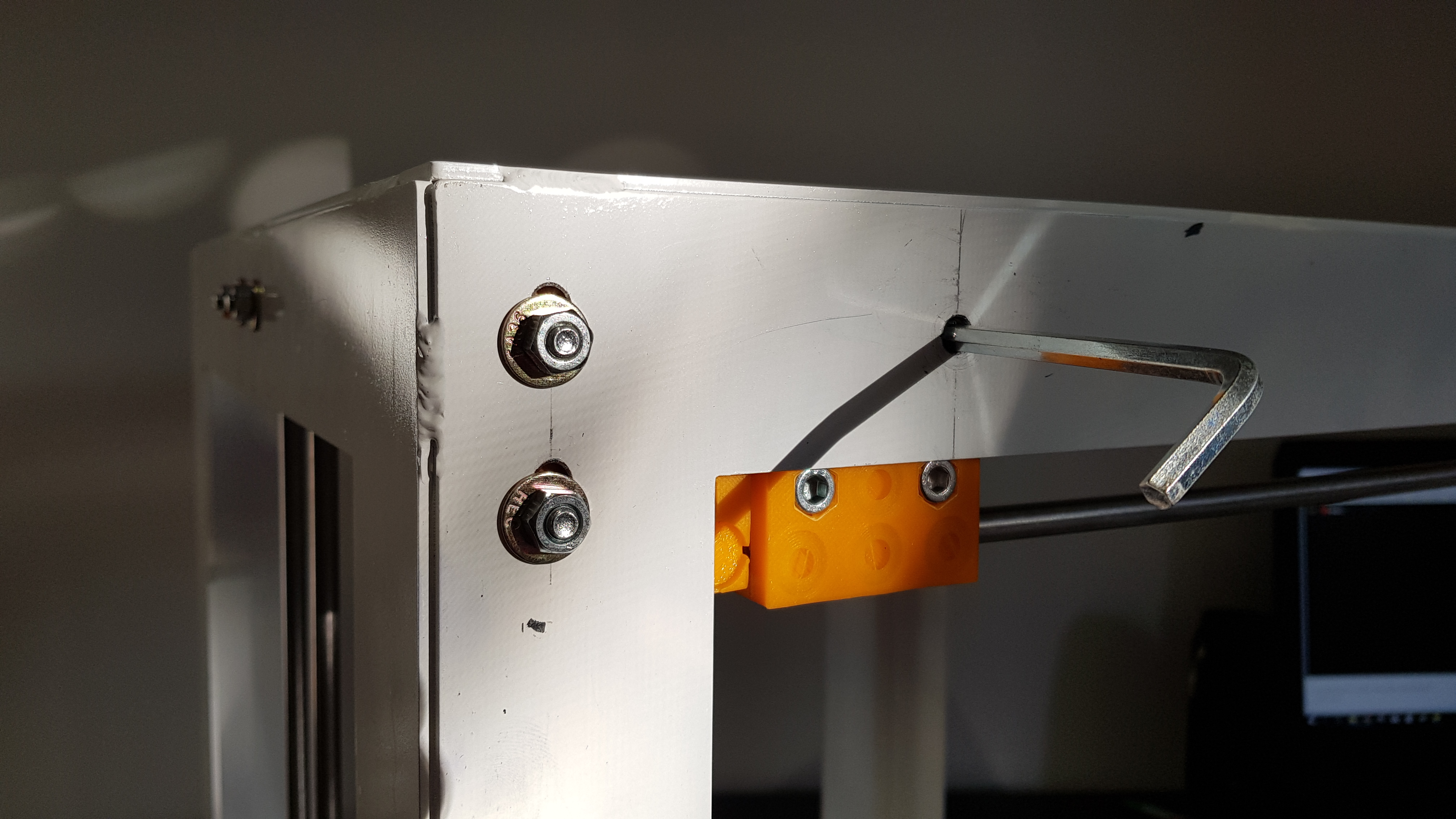
| 05:20, 6 January 2018 | Install x.jpg (file) |  |
2.56 MB | Access hole to tighten the bottom screw holding X-axis to the carriage. | 1 |
| 05:23, 6 January 2018 | Axes configuration.jpg (file) |  |
2.28 MB | Positions of axes and motors. | 1 |
| 05:31, 6 January 2018 | Termistor connector.jpg (file) |  |
2.34 MB | EO and HBP termistors in one connector. Recycle. | 1 |
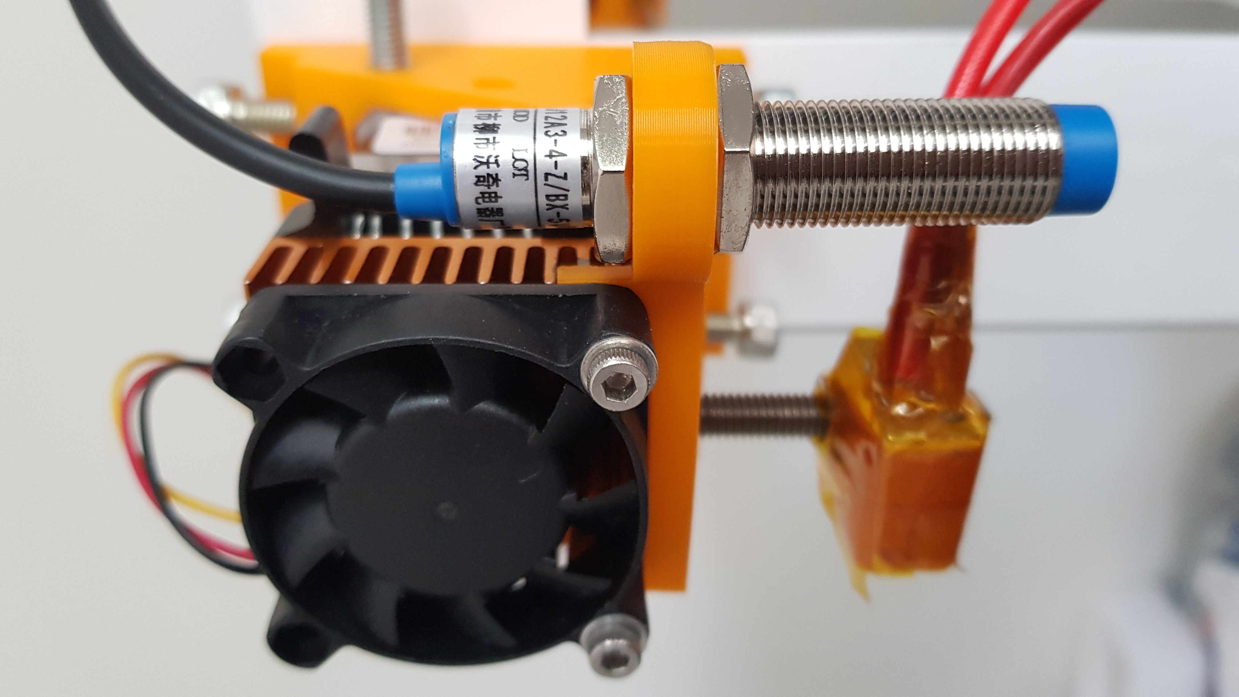
| 05:34, 6 January 2018 | Inductive install.jpg (file) |  |
2.66 MB | Installing inductive sensor | 1 |
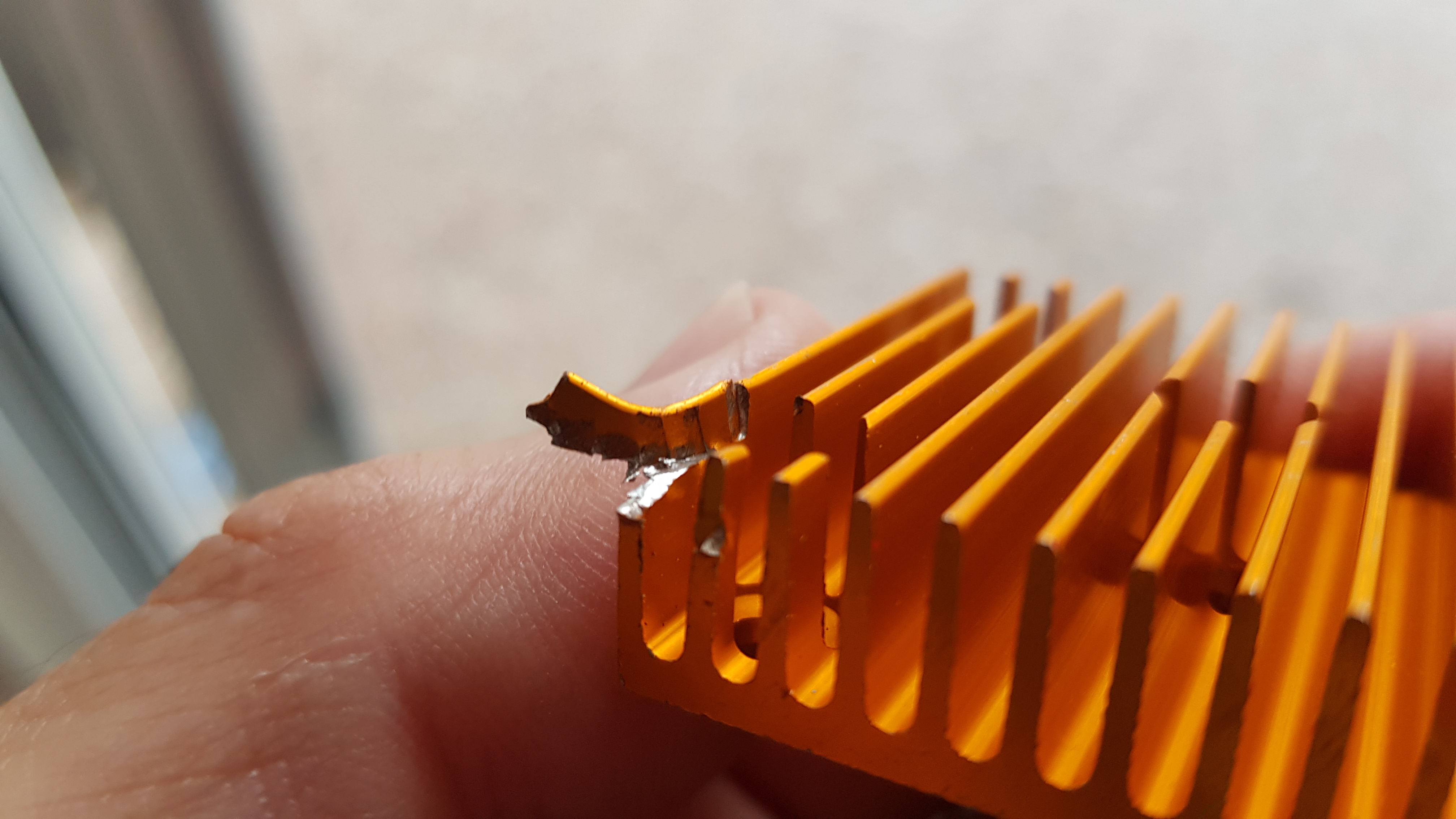
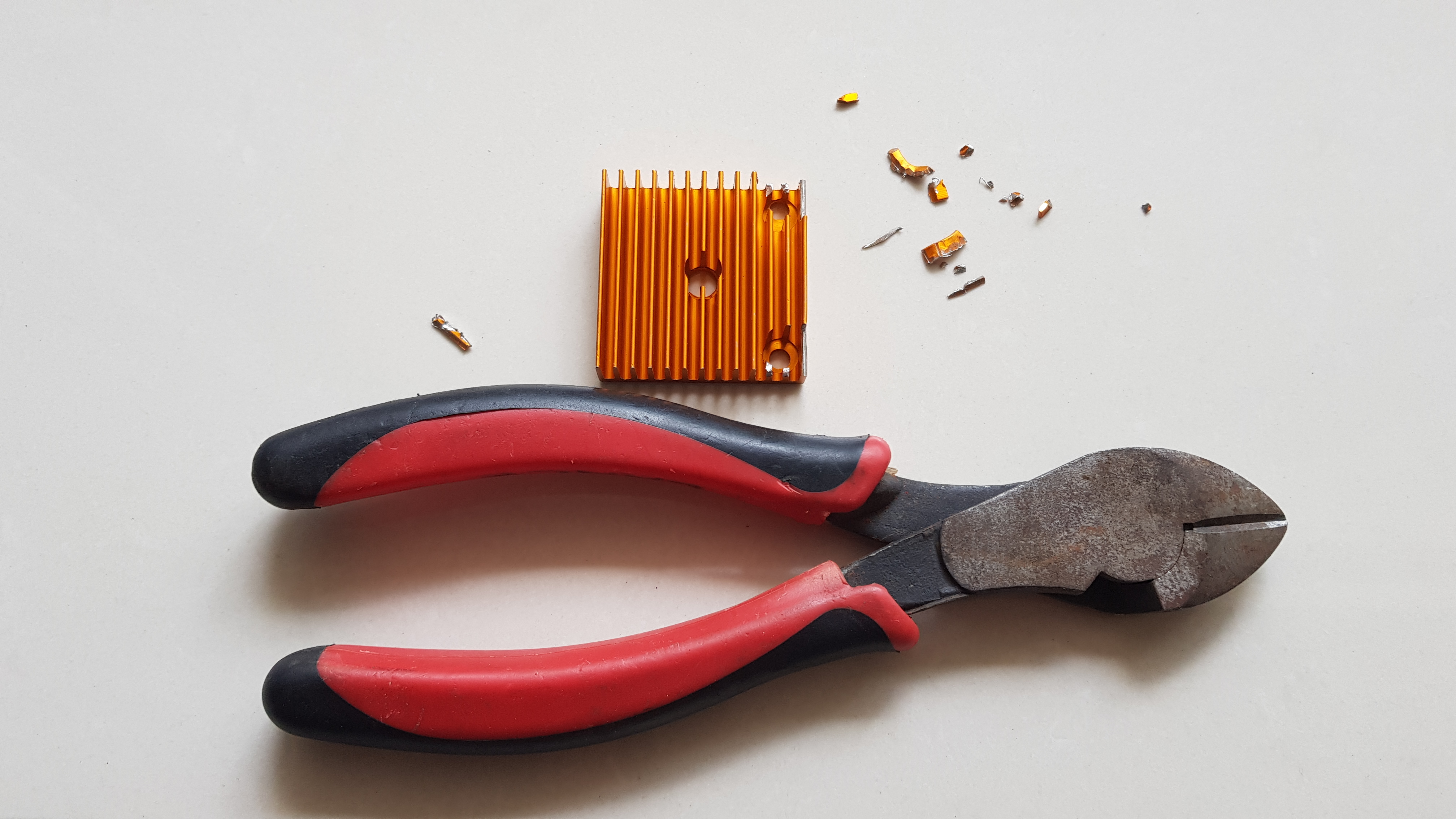
| 05:37, 6 January 2018 | Heat sink ext.jpg (file) |  |
2.23 MB | Trimming extruder heat sink | 1 |
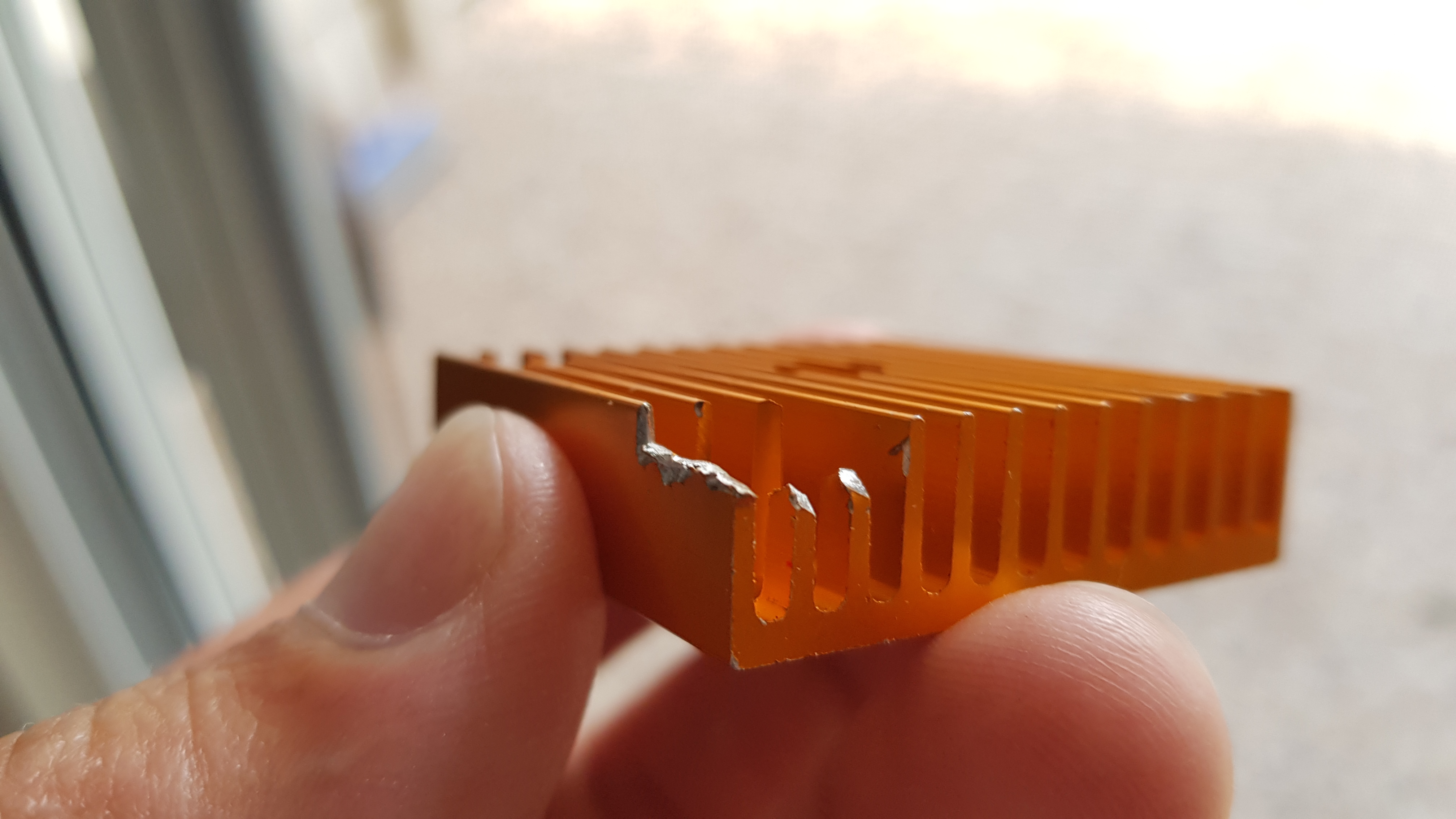
| 05:38, 6 January 2018 | Heat sink ext00.jpg (file) |  |
2.08 MB | Trimmed extruder heat sink | 1 |
| 05:40, 6 January 2018 | Heat sink ext01.jpg (file) |  |
1.98 MB | Vanes | 1 |
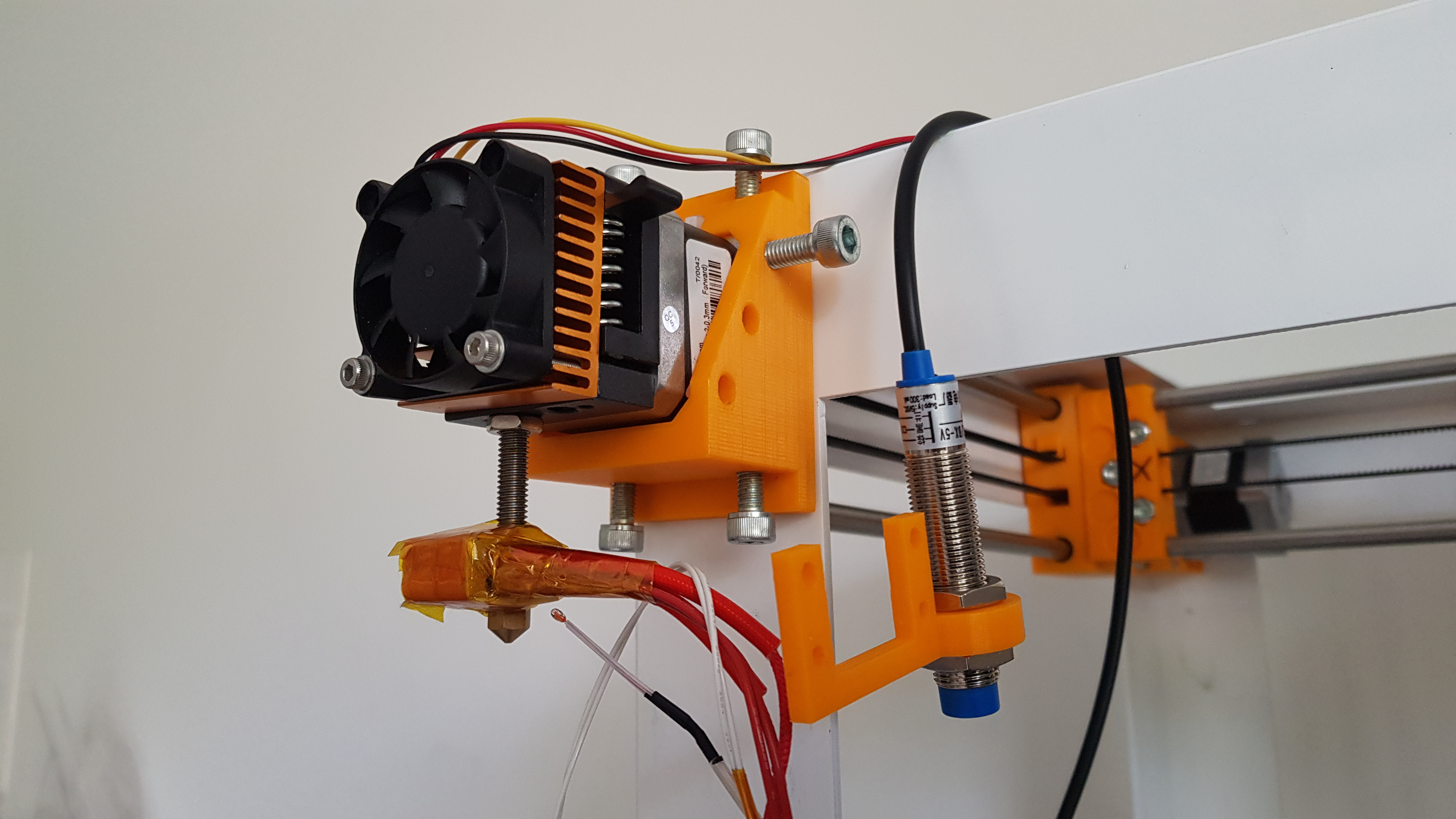
| 05:42, 6 January 2018 | Sensor on.jpg (file) |  |
2.75 MB | Inductive sensor in place. | 1 |
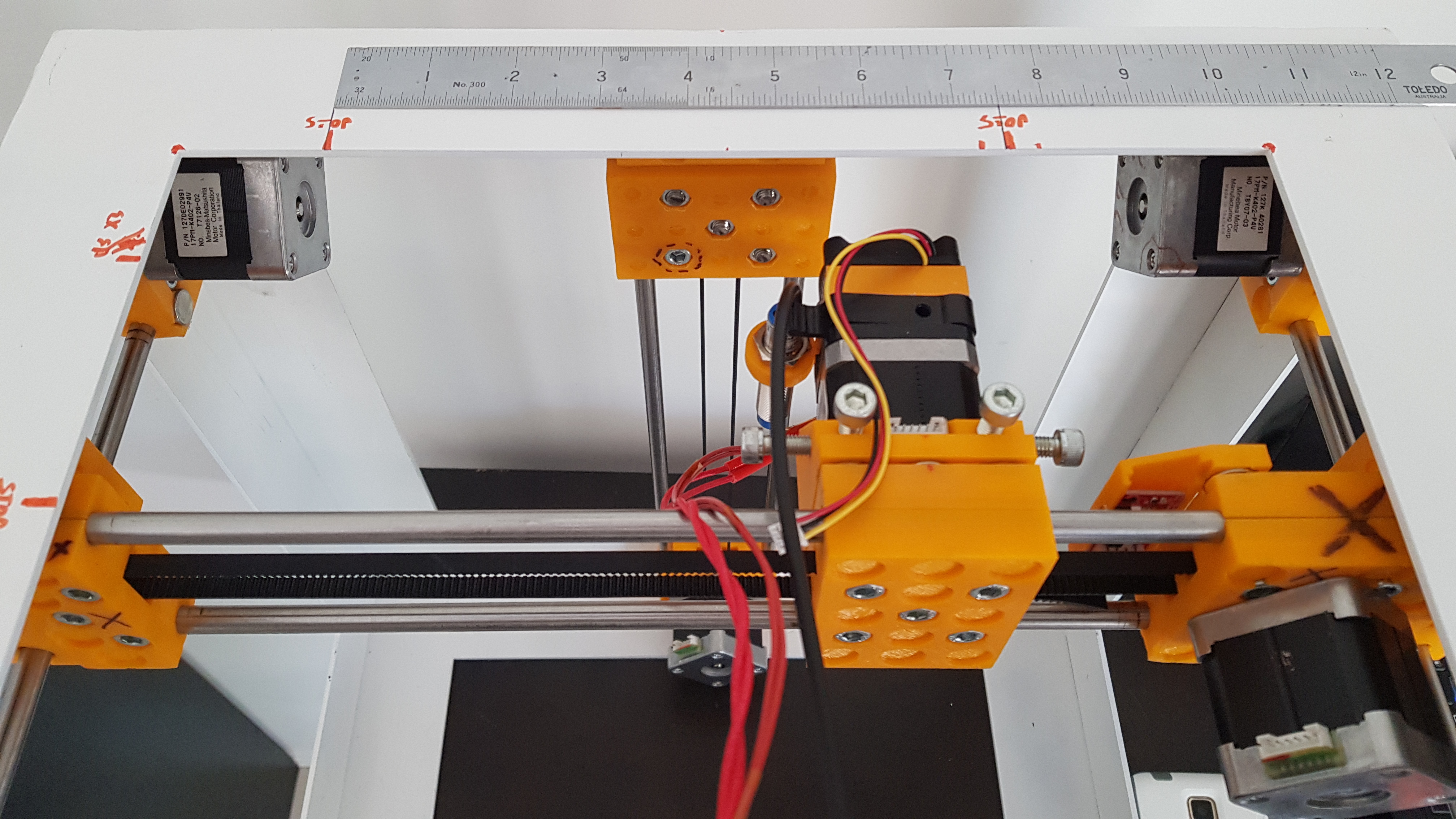
| 05:45, 6 January 2018 | Range X.jpg (file) |  |
2.87 MB | Range of movement on X-axis. 191 mm | 1 |