Boundary Layer Turbine: Difference between revisions
| Line 1: | Line 1: | ||
=Design Rationale= | =Design Rationale= | ||
Drawings by Dan Granett, Granett Engineering: | Drawings by Dan Granett, [http://proto.dangyro.com/ Granett Engineering]: | ||
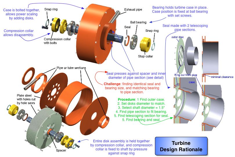
This is an external combustion engine with proven efficiencies of 25% for un-optimized models. A working fluid spins this turbine by means of surface friction. When the disk spacing is small (on the scale of a millimeter), energy transfer from the working fluid to the disks can be efficient. Design rationale: | This is an external combustion engine with proven efficiencies of 25% for un-optimized models with steam (Rice, Warren, ''Transactions of the ASME, Journal of Engineering and Power'', January 1965, pp. 28-36). A working fluid spins this turbine by means of surface friction. When the disk spacing is small (on the scale of a millimeter), energy transfer from the working fluid to the disks can be efficient. Design rationale: | ||
[[Image:BLT_DR.jpg]] | [[Image:BLT_DR.jpg]] | ||
Revision as of 18:33, 26 January 2008
Design Rationale
Drawings by Dan Granett, Granett Engineering:
This is an external combustion engine with proven efficiencies of 25% for un-optimized models with steam (Rice, Warren, Transactions of the ASME, Journal of Engineering and Power, January 1965, pp. 28-36). A working fluid spins this turbine by means of surface friction. When the disk spacing is small (on the scale of a millimeter), energy transfer from the working fluid to the disks can be efficient. Design rationale:
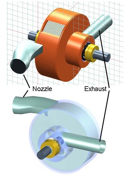
Working fluid (such as steam) enters tangentially to the disks through a nozzle:
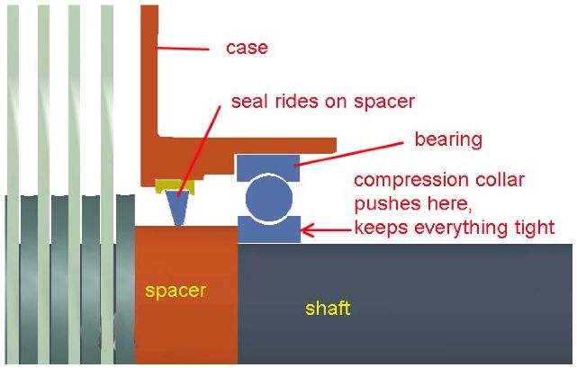
Bearings must be protected from the working fluid with a shaft seal seal:
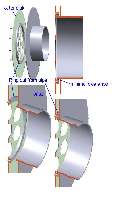
Working fluid must be prevented from escaping past the outer disks so that it can transfer its energy effectively to all the disks. To do this, we put in a ring seal:


