The Liberator Packing List: Difference between revisions
Jump to navigation
Jump to search
No edit summary |
No edit summary |
||
| Line 1: | Line 1: | ||
{{Category=CEB press}} | |||
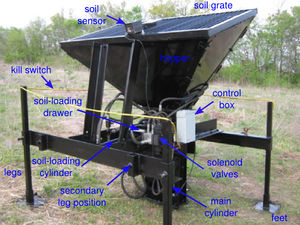
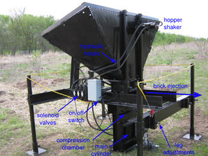
The first step in assembling The Liberator is unpacking the crate, in the reverse order as shown on the [http://openfarmtech.org/weblog/?p=1967 blog]. First, assess that you can identify all the following parts. The machine labels in Fig. 2 and 3 and [http://openfarmtech.org/weblog/?p=1749 blog post] should help. | The first step in assembling The Liberator is unpacking the crate, in the reverse order as shown on the [http://openfarmtech.org/weblog/?p=1967 blog]. First, assess that you can identify all the following parts. The machine labels in Fig. 2 and 3 and [http://openfarmtech.org/weblog/?p=1749 blog post] should help. | ||
| Line 49: | Line 50: | ||
#Soil sensor assembly (Fig. 16) | #Soil sensor assembly (Fig. 16) | ||
#Controller box and cord (Fig. 17) | #Controller box and cord (Fig. 17) | ||
Revision as of 17:29, 8 February 2011
The first step in assembling The Liberator is unpacking the crate, in the reverse order as shown on the blog. First, assess that you can identify all the following parts. The machine labels in Fig. 2 and 3 and blog post should help.
The packing list is:
- Hopper sheet metal (4)
- Frame with main cylinder
- Soil grate
- Arms (2) - primary
- Arms (2) - secondary - the ones with the leg holders
- Soil loading drawer
- Legs (4)
- Feet (4)
- Back hopper supports (2)
- Front hopper supports (2)
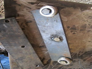
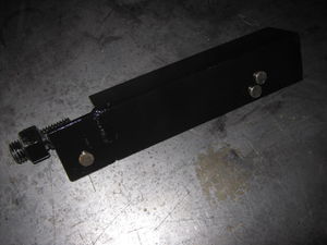
- Roller guides (2) (Fig. 4)
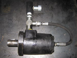
- Shaker motor (Fig. 5)
- Shaker motor return line assembly with needle valve (Fig. 5)
- Secondary cylinder
- Soil shaker assembly (Fig. 6)
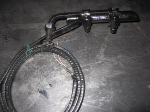
- Secondary cylinder sensor assembly (Fig. 7)
- Grate mounts (4 pieces) (Fig. 8)
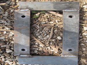
- Hopper mounting plate (Fig. 9)
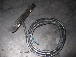
- Main cylinder sensor (Fig. 10)
- Secondary cylinder sensor (Fig. 11)
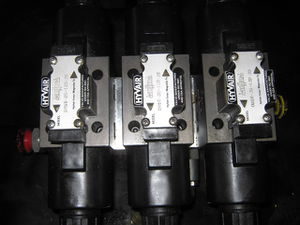
- Solenoid valve (Fig. 12)
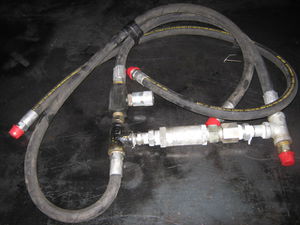
- Secondary cylinder hose assembly (Fig. 13)
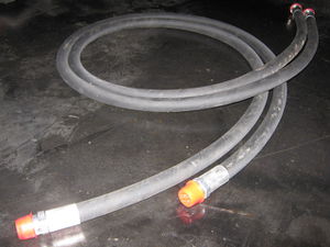
- Shaker hoses and main cylinder hoses, 6 foot long (4) (Fig. 14)
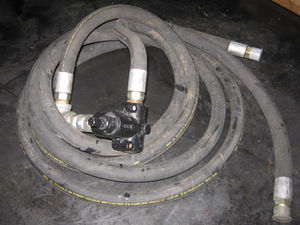
- Main hose assembly (Fig. 15)
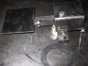
- Soil sensor assembly (Fig. 16)
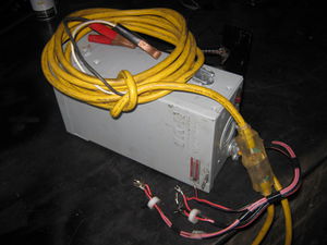
- Controller box and cord (Fig. 17)
