Ron Broberg/Projects/Variable Voltage Regulator: Difference between revisions
Jump to navigation
Jump to search
Ron Broberg (talk | contribs) (Created page with "This variable voltage supply is built on the [http://en.wikipedia.org/wiki/LM317| LM317] variable voltage regulator integrated circuit. It is based on one by [http://www.sentex.c...") |
(No difference)
|
Latest revision as of 23:20, 24 July 2011
This variable voltage supply is built on the LM317 variable voltage regulator integrated circuit. It is based on one by van Roon. The left hand circuit in TvR's original can be replaced with an ATX computer power supply. The right hand circuit in TvR's original was replaced by a handheld voltmeter. This variable voltage regulator supplies 1.2VDC - 32VDC at about 1.5 amps.
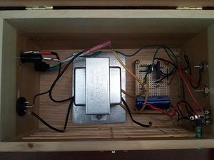
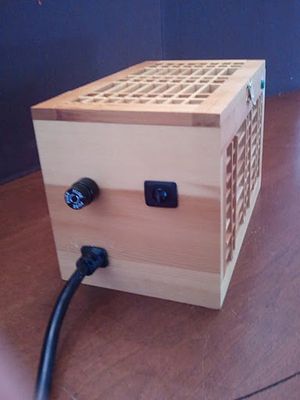
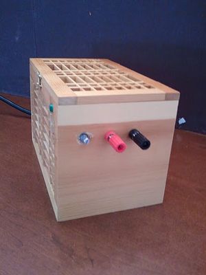
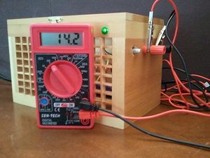
Photographs
Bill of materials
Power supply (in)
- BR1 = Bridge Rectifier
- TR1 = Transformer 24VAC, 3A
- S1 = On-Off toggle switch
- Fuse = 115V, 500mA, slow-blow
- FuseHolder, enclosure, knob for P1
- Plug = 3-wire plug & cord
Voltage Regulator
- IC1 = LM317, adjustable regulator
- D1 = 1N4001
- C1 = 1000uF/63V, electrolytic (see text)
- C2 = 0.1uF (100nF), ceramic
- C3 = 1uF/40V, electrolytic
- R1 = 22K (18K in orig)
- R2 = 220 ohm
- R3 = 27K
- Led1 = Led of your choice
- P1 = 5K, potentiometer
- Red and Black Banana Jacks, coolrib for IC1.
Voltmeter (Not used)
- V = Meter, 30V, Ri = 85 ohm
- P2 = 10K, Bourns trim-pot


