CEB Press/Manufacturing Instructions/Frame with main cylinder: Difference between revisions
Jump to navigation
Jump to search
William Neal (talk | contribs) No edit summary |
William Neal (talk | contribs) No edit summary |
||
| Line 50: | Line 50: | ||
[[Image:Form_Together.jpg|200px|Form Pieces Together]] | [[Image:Form_Together.jpg|200px|Form Pieces Together]] | ||
<html><h3>Step 3: Line the Vertical Beams along the Form and C-Clamp them in Place</h3></html> | |||
[[Image:Vertical_Beams.jpg|200px|Align Vertical Beams]] | |||
<html><h3>Step 4: Place One Each of the Upper and Lower Cross Beams</h3></html> | |||
[[Image:Cross_Beams.jpg|200px|Cross Beams]] | |||
<html><h3>Step 5: Flip the Frame</h3></html> | |||
[[Image:Flip_Frame.jpg|200px|Flip Frame]] | |||
Revision as of 00:58, 20 August 2011
Main > Housing and construction > CEB Press > CEB press building instructions
Tools Required
- torch
- hole punch
Materials Required
- 6 inch heavy (7/16") u-channel - ( 20 ft )
- 3/4" x 2" Bolts (32))
- 3/4" Nuts (32)
- 3”x3”x1/2” (8) (cylinder mounts for both cylinders)
- 1” shaft, 6” long (main cylinder mount)
- 5 X 8 3000PSI Welded Cross-Tube Hydraulic Cylinder Buy
Fabrication Steps
Step 1: Cut pieces
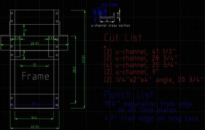
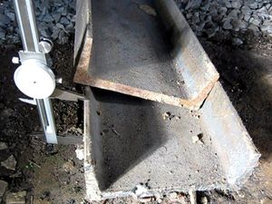
Cut the following pieces out of the 6 inch heavy (7/16") u-channel steel:
- A - 2 pieces, 44"
- B - 2 pieces, 28 3/4"
- C - 4 pieces, 20 3/4"
- D - 2 pieces, 9"
Cut the following pieces out of 1/4X2"X4" angle steel:
- E - 2 pieces 20 3/4"
Cut the following pieces out of 1/4" sheet steel:
- 2 pieces 10”x18” (bent (90 degrees???) 1.5” off the edge the long way)
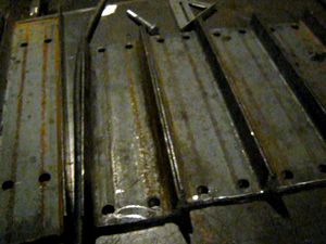
Step 2: Punch holes
- A - 1" from the tip of the edge, in the edges of 41 1/2" upright pieces at the following locations: 1", 5", 36.5", 40.5"(more to follow)
- B - Four holes in each of the 28 3/4" pieces such that they are 19.4" apart on the long axis and 4"(?not sure) apart on the short axis. They should form a centred rectangle parallel to each of the 26" pieces.
- C - Four holes in each of the 20 3/4" pieces such that they are 19.4" apart on the long axis and 4"(?not sure) apart on the short axis. They should form a centered rectangle parallel to each of the 18" pieces.
- D -
- E -
Step 3: Bolt pieces together
Step 4: Prepare Hydraulic Cylinder
Diagrams
Step 1: Gather the Form Pieces
Step 2: Put the Form Pieces Together
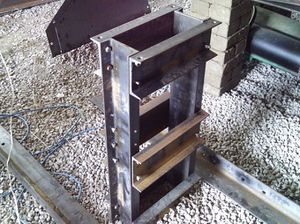
Step 3: Line the Vertical Beams along the Form and C-Clamp them in Place
Step 4: Place One Each of the Upper and Lower Cross Beams
Step 5: Flip the Frame
This diagram shows the pieces needed for the frame. Click to enlarge:

Video Explantion


