CNCCMV2: Difference between revisions
| Line 154: | Line 154: | ||
*The idea here is that the motor can be mounted on the angle; meanwhile the driveshaft can be held inside the rectangular bar by 2 ball bearings, 1 at each end. The flat bar is there to secure the angle and rect. bar together. | *The idea here is that the motor can be mounted on the angle; meanwhile the driveshaft can be held inside the rectangular bar by 2 ball bearings, 1 at each end. The flat bar is there to secure the angle and rect. bar together. | ||
*However, if the desire is to hold the driveshaft at the top and bottom, a C-Channel can replace the block, with various implications. | |||
*Here is a visual example: | |||
[[Image: spindlechannel.jpg|500px]] | |||
=Sourcing= | =Sourcing= | ||
Revision as of 03:15, 25 March 2012
Action Plan
- Conceptual Design
- Specific Design
- Sourcing
- Manufacturing
- Testing
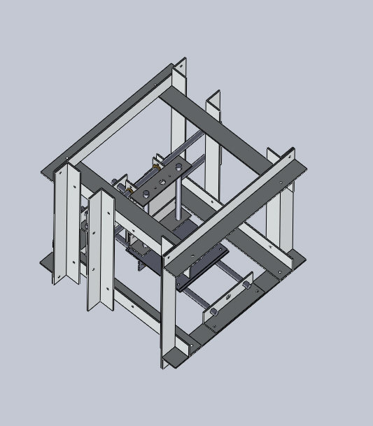
CAD of Mobile Bed Design (In Progress)
CAD of Mobile Gantry Design (In Progress)
Connexions Modules
How to Use the CNC Circuit Mill
How to Design a CNC Circuit Mill
Making the Arduino IDE Work on Linux
Key Performance Specifications
- X Axis Travel Range = 20cm
- Y Axis Travel Range = 20cm
- Z Axis Travel Range = 5cm
- Step Motor Torque at 12VDC = 3.2kg-cm
- Spindle Max Rotation Speed = 22600rpm no-load
- Spindle Motor Torque at 24VDC = 88.5g-cm at max efficiency
- Workpiece Holding Mechanism = Linear Bolt and Tensioning Nut
- For Prototype II, define goals based on study of industry standards. Include desired precision + accuracy + speed.
- Minimum step size for each axis plus variance
- Repeatability of motion (drift) (determined by going to certain locations a large number of times)
- Minimum spacing between traces (determined by minimum allowable size of bit + precision)
- Minimum trace size possible
- Goal: repeatability is as good as step size - ie, all inaccuracy is negligible compared to step size, and zero backlash at all practical milling speeds.
- Define practical milling speed range based on substrate
Key Design Specifications
- Step Motor Axis Drive
- Rotary-to-Linear Motion Converting Stainless Steel Leadscrew and Wear-compensating Leadscrew Nut
- Anti-friction Bronze Sleeve Bearings
- Precision Stainless Steel Axis-Supporting Shafts
- Versatile Holding Platform with Magnets
- Brushed DC Motor Spindle Drive
- Precision Stainless Steel Spindle Shaft
- Computer to Microcontroller to Stepper Driver Electronics Pathway
- Gcode Streamer to Gcode Interpreter Software Pathway
Cost
- Cost values in USD. In practice, some items must be purchased in greater quantity than necessary; the following values are equalized to the correct quantities. List excludes tools and shipping.
- Cube Frame Metal =
- Axes Structure Metal =
- Metal Shafts = 124
- Leadscrews and Leadscrew Nuts = 240
- Bearings = 65
- Fasteners = 70
- Control and Drive Electronics = 130
- Power Supply = 35
- Software = Open Source
- Total =
X-Axis Frame Design Rationale
- Start by assuming that the x-axis frame needs to support a pair of precision shafts and allow mounting of the working platform and stepper motor with leadscrew.
- The working platform has to be some sort of flat sheet or plate.
- Some sort of rectangular support structure seems a good start, with a total part count of 5.
- Here is an visual example using 1 plate and 4 rectangular bars:
- This is rigid and has space at the sides for gantry mounting, but bulky. We notice that a lot of material is still being used despite the low part count. Keep in mind that part count and material volume, future design implications, and ease-of-manufacturing must all be considered separate, though interrelated factors in effective design.
- If we use only 2 rectangular bars (for supporting the precision shafts), then we can save on material volume by using 2 angles as structural supports.
- Here is an visual example using 1 plate, 2 rectangular bars, and 2 angles:
- This is relatively volume-efficient, with plenty of open space at the side for gantry mounting. The major concern with this design is that the resistance to force vectors is heavily dependent on the angle supports, which significantly lose mechanical advantage as the rectangular bars get taller. Low-profile setups will be best for this design.
- Here is another take on the 1 plate, 2 rectangular bar, 2 angle setup. What if the angles were to mount the precision shafts instead of the rectangular bars?
- The major concern with this design is the vulnerability to forces with strong vectors along the horizontal plane. Again, low-profile setups will be best.
- For completeness of the practical variations of the 5-part x-axis frame, consider the use of 4 angles and 1 plate:
- The major concern with this setup is that the angles, though volume-efficient, will not provide enough rigidity at their 4 junctions.
Spindle Design Rationale
- The spindle system needs to mount a motor and hold the a driveshaft with 2 bearings for over 20,000 rpm.
- The easiest way to ensure alignment of the 2 bearings is to house the driveshaft within 1 part. Meanwhile, the motor can be mounted on another. Both parts need to be secured together in position.
- Let's start with 1 rectangular bar, 1 flat bar, and 1 angle:
- The idea here is that the motor can be mounted on the angle; meanwhile the driveshaft can be held inside the rectangular bar by 2 ball bearings, 1 at each end. The flat bar is there to secure the angle and rect. bar together.
- However, if the desire is to hold the driveshaft at the top and bottom, a C-Channel can replace the block, with various implications.
- Here is a visual example:
Sourcing
- Spreadsheet File
LINK HERE
- Prototyping Spreadsheet
- To edit or download the spreadsheet, click on the following link.
https://docs.google.com/spreadsheet/ccc?key=0AlpsBarfpPkzdFk5aDY3dHM0eEhfZHNkWVppdV9EelE
Build Process
+1
Structure
- 400mm x 1.5" x 1.5" x 0.125" Steel Angle (14)
- 140mm x 1.5" x 1.5" x 0.125 Aluminum Angle (12)
- 35mm x 1.5" x 1.5" x 0.125 Aluminum Angle (3)
- Single Point Template
- Double Point Template
- Frame Template
- Axis Template
- Mount Template
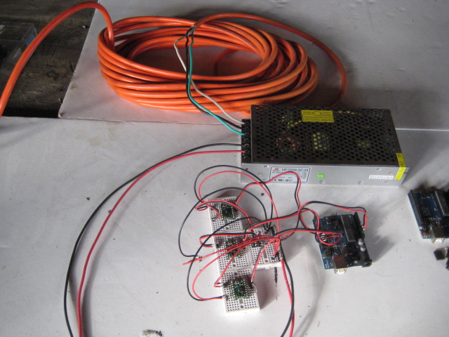
Electronics
+1
Soldering Stepper Driver Pins
- Insert the short end of the male headers into the stepper driver board from the bottom, then pressfit the headers into the small breadboard for holding.
- Apply flux to all header connections
- Apply solder to the tip of the soldering iron
- Solder header connections at opposite corners of the stepper driver board for stability, reapplying solder to and cleaning the soldering iron tip as necessary; repeat for the remaining header connections.
Soldering Connectors
Wiring
-1
Software
+1
Ubuntu 10.04 LTS 32-Bit
+1
Getting Git
- Open Terminal and type:
sudo apt-get install git-core
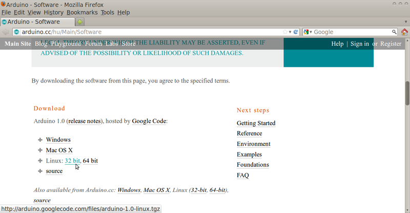
Getting Arduino Integrated Development Environment
- Go to this webpage:
http://arduino.cc/hu/Main/Software
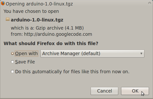
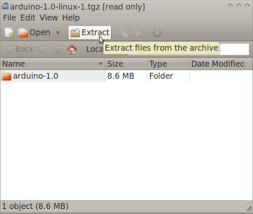
- Download the Linux 32-bit version of Arduino IDE to a directory of your choosing
Compatibilizing Arduino IDE
- The following steps are a summary of the information in this webpage:
http://www.pluggy.me.uk/arduino-ubuntu/
- Open System>Administration>Synaptic Package Manager, then type your password
- In Synaptic Package Manager, search for jre, then mark for installation the item with the following name:
Openjdk-6-jre
- Note: marking these items will bring up other packages also to be marked. Click "mark" during these times.
- In Synaptic Package Manager, search for gcc-avr, then mark for installation the item with the following name:
gcc-avr
- In Synaptic Package Manager, search for avr-libc, then mark for installation the item with the following name:
avr-libc
- In Synaptic Package Manager, click "Apply"
- Restart your computer
Getting RUBY Programming Language
- Open Terminal and type:
sudo apt-get install ruby1.9.1
- Restart the computer for the changes to take place
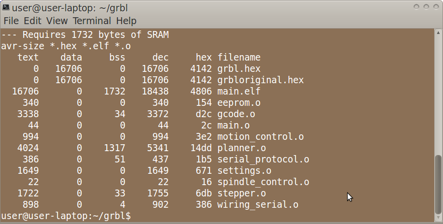
Getting GRBL Files
- Open Terminal and type:
git clone https://github.com/damellis/grbl.git grbl
Getting Gctrl
- Open Terminal and type:
git clone https://github.com/damellis/gctrl.git gctrl
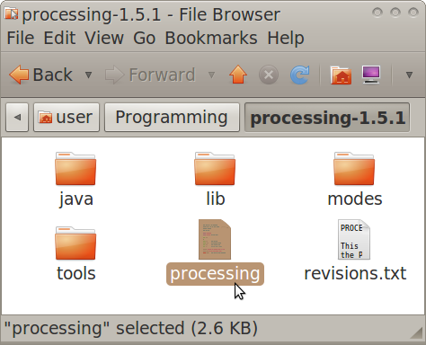
Getting Processing
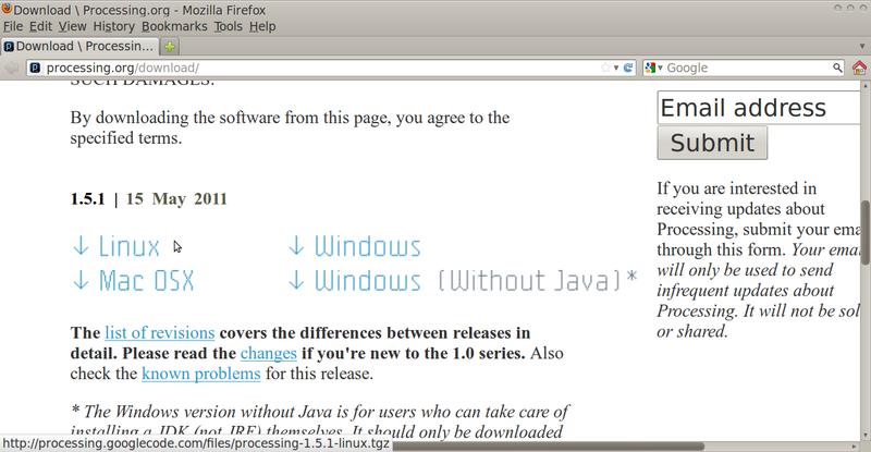
- Go to this webpage:
http://processing.org/download/
- Download the latest version of Processing to a directory of your choosing
Moving RXTX files
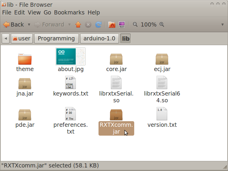
- Navigate to the Arduino IDE folder>lib.
- Copy RXTXcomm.jar
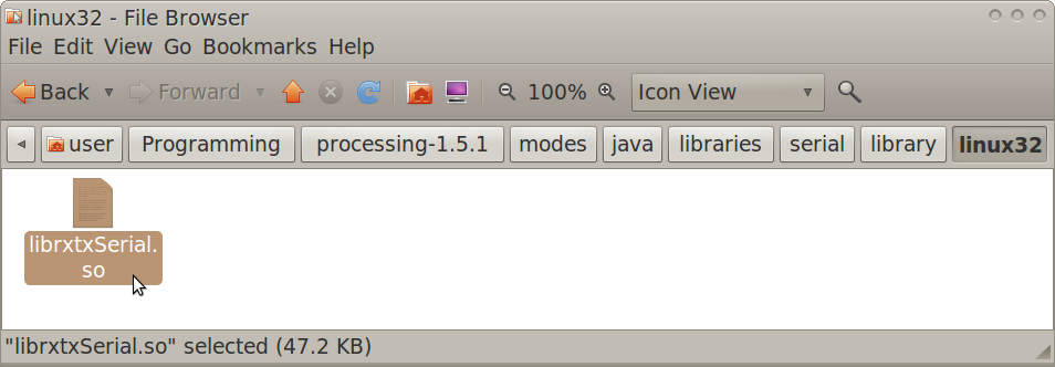
- Navigate to the Processing folder>modes>java>libraries>serial>library
- Paste RXTXcomm.jar, replacing the existing version
- Navigate to the Arduino IDE folder>lib
- Copy librxtxSerial.so
- Navigate to the Processing folder>modes>java>libraries>serial>library>Linux32
- Paste librxtxSerial.so, replacing the existing version
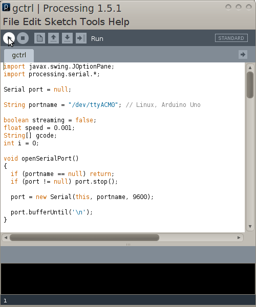
Modifying Gctrl
- Open the Gctrl folder
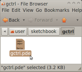
- Open gctrl.pde in gedit
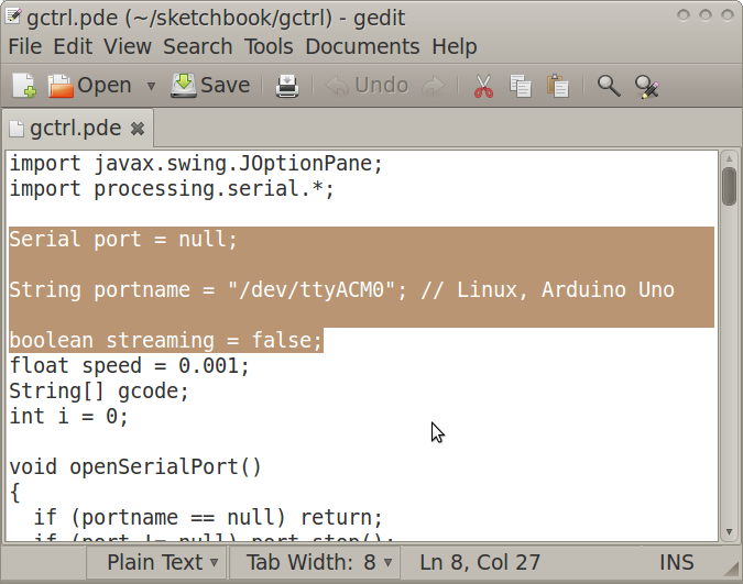
- Change a part of the code as annotated in the following:
Serial port = null; //change starts
String portname = "/dev/ttyACM0"; // Linux, Arduino Uno
//change ends
boolean streaming = false;
Modifying GRBL Files
- Navigate to the GRBL folder
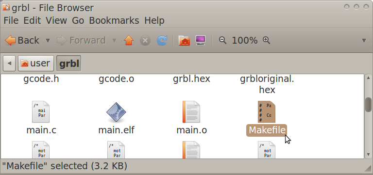
- Open "Makefile" in gedit
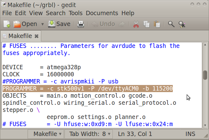
- Edit the PROGRAMMER line as:
PROGRAMMER = -c stk500v1 -P /dev/ttyACM0 -b 115200
Flashing GRBL
- Open Terminal and navigate to the GRBL folder (ex. by using the "ls" and "cd" commands)
- In Terminal, type:
make clean
- In Terminal, type:
make
- Connect the Arduino Uno to the computer via USB cable
- In Terminal, type:
make flash
- Disconnect the Arduino Uno
Running Gctrl
- Navigate to the Processing folder
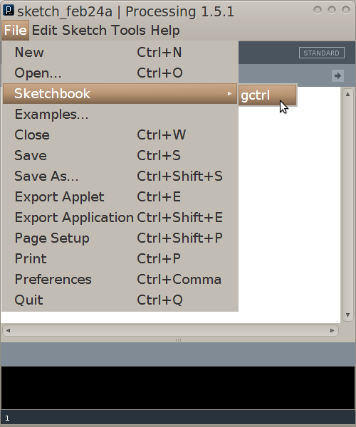
- Open and run Processing, setting the sketchbook folder as the folder in which the gctrl folder exists
- In Processing, open gctrl using File>Sketchbook>
- Connect the Arduino Uno to the computer via USB cable
- In Processing, run gctrl using Sketch>Run
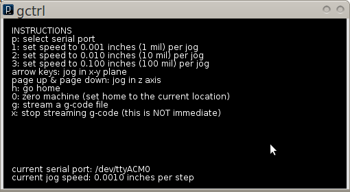
- Now the Gctrl GUI window should pop up
- Note: For certain functions of gctrl, press and hold down the key for the popup windows to populate.
Determining GRBL Configuration Changes Required
- Go to the following webpage:
http://dank.bengler.no/-/page/show/5474_configuringgrbl?ref=mst
Modifying GRBL Settings
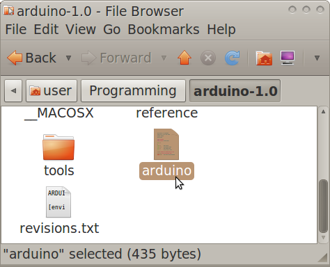
- Navigate to the Arduino IDE folder
- Double-click "Arduino" then click "run" in the popup window
- Note: you may want to create a quick launcher for the Arduino IDE
- Connect the Arduino Uno to the computer via USB cable
- In Arduino IDE, open Tools>Serial Monitor
- Note: the Serial Monitor window should pop up and you should see the following:
Grbl 0.6b
'$' to dump current settings
- In the Serial Monitor, change the left drop-down setting to the following:
Both NL & CR
- In the Serial Monitor, type the following in the command line:
$
- Note: you should now see the following:
$0 = 157.480 (steps/mm x)
$1 = 157.480 (steps/mm y)
$2 = 157.480 (steps/mm z)
$3 = 10 (microseconds step pulse)
$4 = 500.0 (mm/min default feed rate)
$5 = 600.0 (mm/min default seek rate)
$6 = 0.100 (mm/arc segment)
$7 = 0 (step port invert mask. binary = 0)
$8 = 25.0 (acceleration in mm/sec^2)
$9 = 225.0 (max instant cornering speed change in delta mm/min)
'$x=value' to set parameter or just '$' to dump current settings
- In the Serial Monitor, type commands as necessary in the following format, where "X" and "Y" are numbers:
$X = Y
-3
Design Modifications
+1
Modularity
- Different step motors and drive mechanisms can be mounted onto the axis support angles via mounting holes
- Different frames can be used, provided they have precise mounting holes for the axis support angles
- Different holding platforms can be used, provided they have mounting holes for the X axis moving angles
- Different spindle setups can be used, provided they have mounting holes for the Z axis moving angles
- Different stepper driver boards and power supplies can be used, provided they have compatible performance specifications within the electronics system
Scaling
- Scaling mainly consists of changing the size of the frame (to affect travel ranges) and the type of step motors (to affect travel rates)
- Other discrete components such as fasteners, leadscrews, and shafts need only be scaled if necessary for functionality or certain desired performance specifications
- The travel range calculation for the X axis:
(X Travel Range) = (Distance Between 2 Parallel Frame Angles Along Horizontal Plane) - (Length of Platform Along Axis)
- The travel range calculation for the Y axis:
(Y Travel Range) = (Distance Between 2 Parallel Frame Angles Along Vertical Plane) - (Length of Z Support Angles Along Axis)
-1
Usage
- Circuit Schematic to Gcode File Toolchain
- See following link for list of electronic design suites:
http://en.wikipedia.org/wiki/Comparison_of_EDA_software
- PCB-Gcode Optimizer
http://cnc.goodbits.net/wiki/index.php5/Pcb-gcode_optimizer
http://www.millpcbs.com/index.php?option=com_content&view=article&id=10&Itemid=44
Maintenance
Distributive Enterprise
+1
GVCS Product Ecology
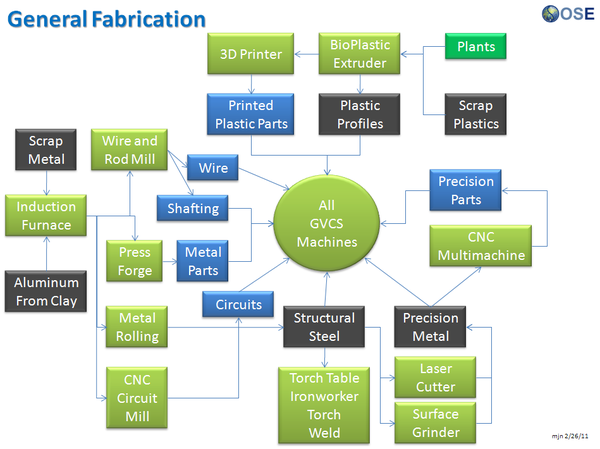
Uses
- Induction Furnace - Steel
- Aluminum Extractor - Aluminum
- Metal Roller - Fasteners, Metal Angles, and Flats
- Rod and Wire Mill - Wires, Shafts
- CNC Multimachine - Bearings, Leadscrews, Leadscrew Nuts
- Motors - XYZ Movement
- CNC Circuit Mill - Control Circuit Boards
- Universal Power Supply - Power
Creates
- Milled Circuit Boards
See Product Ecologies for more information.
