CNCCMV2: Difference between revisions
(→Wiring) |
|||
| Line 134: | Line 134: | ||
=Soldering Connectors= | =Soldering Connectors= | ||
[http://opensourceecology.org/wiki/CNCCMV2/Electronics Electronics] | |||
[ | |||
=Software= | =Software= | ||
Revision as of 01:07, 31 March 2012
Action Plan
- Conceptual Design
- Specific Design
- Sourcing
- Manufacturing
- Testing
- Documentation During All of the Above
Design Rationale
CAD and 2D Fabrication Drawings
Connexions Modules
How to Use the CNC Circuit Mill
How to Design a CNC Circuit Mill
Making the Arduino IDE Work on Linux
Key Performance Specifications
- X Axis Travel Range = 20cm
- Y Axis Travel Range = 20cm
- Z Axis Travel Range = 5cm
- Step Motor Torque at 12VDC = 3.2kg-cm
- Spindle Max Rotation Speed = 22600rpm no-load
- Spindle Motor Torque at 24VDC = 88.5g-cm at max efficiency
- Workpiece Holding Mechanism = Linear Bolt and Tensioning Nut
- For Prototype II, define goals based on study of industry standards. Include desired precision + accuracy + speed.
- Minimum step size for each axis plus variance
- Repeatability of motion (drift) (determined by going to certain locations a large number of times)
- Minimum spacing between traces (determined by minimum allowable size of bit + precision)
- Minimum trace size possible
- Goal: repeatability is as good as step size - ie, all inaccuracy is negligible compared to step size, and zero backlash at all practical milling speeds.
- Define practical milling speed range based on substrate
Key Design Specifications
- Step Motor Axis Drive
- Rotary-to-Linear Motion Converting Stainless Steel Leadscrew and Wear-compensating Leadscrew Nut
- Anti-friction Bronze Sleeve Bearings
- Precision Stainless Steel Axis-Supporting Shafts
- Versatile Holding Platform with Magnets
- Brushed DC Motor Spindle Drive
- Precision Stainless Steel Spindle Shaft
- Computer to Microcontroller to Stepper Driver Electronics Pathway
- Gcode Streamer to Gcode Interpreter Software Pathway
Cost
- Cost values in USD. In practice, some items must be purchased in greater quantity than necessary; the following values are equalized to the correct quantities. List excludes tools and shipping.
- Cube Frame Metal =
- Axes Structure Metal =
- Metal Shafts = 124
- Leadscrews and Leadscrew Nuts = 240
- Bearings = 65
- Fasteners = 70
- Control and Drive Electronics = 130
- Power Supply = 35
- Software = Open Source
- Total =
Sourcing
- Spreadsheet File
LINK HERE
- Prototyping Spreadsheet
- To edit or download the spreadsheet, click on the following link.
https://docs.google.com/spreadsheet/ccc?key=0AlpsBarfpPkzdFk5aDY3dHM0eEhfZHNkWVppdV9EelE
Electronics
Soldering Connectors
Software
Ubuntu 10.04 LTS 32-Bit
Move RXTX files to make Arduino boards work with Processing
Modify Gctrl code for Easier Connection with Arduino on Linux
Modify GRBL Files for enabling GRBL flashing to Arduino board on Linux
Determine GRBL Configuration Changes Required
Design Modifications
Modularity
- Different step motors and drive mechanisms can be mounted onto the axis support angles via mounting holes
- Different frames can be used, provided they have precise mounting holes for the axis support angles
- Different holding platforms can be used, provided they have mounting holes for the X axis moving angles
- Different spindle setups can be used, provided they have mounting holes for the Z axis moving angles
- Different stepper driver boards and power supplies can be used, provided they have compatible performance specifications within the electronics system
Scaling
- Scaling mainly consists of changing the size of the frame (to affect travel ranges) and the type of step motors (to affect travel rates)
- Other discrete components such as fasteners, leadscrews, and shafts need only be scaled if necessary for functionality or certain desired performance specifications
- The travel range calculation for the X axis:
(X Travel Range) = (Distance Between 2 Parallel Frame Angles Along Horizontal Plane) - (Length of Platform Along Axis)
- The travel range calculation for the Y axis:
(Y Travel Range) = (Distance Between 2 Parallel Frame Angles Along Vertical Plane) - (Length of Z Support Angles Along Axis)
Usage
- Circuit Schematic to Gcode File Toolchain
- See following link for list of electronic design suites:
http://en.wikipedia.org/wiki/Comparison_of_EDA_software
- PCB-Gcode Optimizer
http://cnc.goodbits.net/wiki/index.php5/Pcb-gcode_optimizer
http://www.millpcbs.com/index.php?option=com_content&view=article&id=10&Itemid=44
Maintenance
Distributive Enterprise
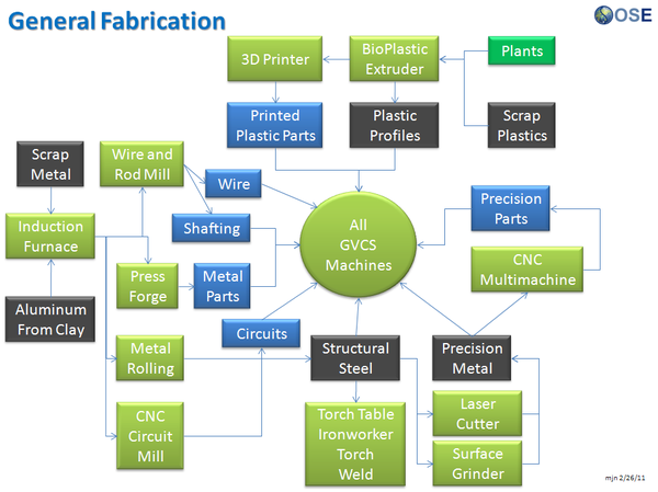
GVCS Product Ecology

Uses
- Induction Furnace - Steel
- Aluminum Extractor - Aluminum
- Metal Roller - Fasteners, Metal Angles, and Flats
- Rod and Wire Mill - Wires, Shafts
- CNC Multimachine - Bearings, Leadscrews, Leadscrew Nuts
- Motors - XYZ Movement
- CNC Circuit Mill - Control Circuit Boards
- Universal Power Supply - Power
Creates
- Milled Circuit Boards
See Product Ecologies for more information.