Cold Saw/V1 Design Rationale: Difference between revisions
< Cold Saw
Jump to navigation
Jump to search
| Line 89: | Line 89: | ||
=Support System= | =Support System= | ||
*2 Shaft Blocks radially support the ends of the | *2 Shaft Blocks radially support the ends of the Support Shaft. | ||
*The Support Shaft is axially held by shaft collars on its outside ends. | *The Support Shaft is axially held by shaft collars on its outside ends. | ||
| Line 98: | Line 98: | ||
*The Bridge Bars span the Main Bar and Support Bar to connect them and add rigidity. | *The Bridge Bars span the Main Bar and Support Bar to connect them and add rigidity. | ||
*[[Image: ColdSawV1Support.png]] | |||
=Drive Assembly= | =Drive Assembly= | ||
Revision as of 02:14, 21 May 2012
Conceptual Parameters
- Baseplate
- 2 Fixed Blocks (mounted to baseplate by XXX, 2 shaft holes, 1 threaded rod hole)
- 1 Moving Nut Block (rides on 2 shafts, driven by a threaded rod that moves a nut welded to the block)
- 2 Shafts (radially held on the Fixed Blocks, axially held by 2 shaft couplings on the outsides of the Fixed Blocks)
- Threaded Rod (radially held on the Fixed Blocks, axially held by 2 thrust washers and 2 shaft couplings on the outsides of the Fixed Blocks, drives a nut welded to the Moving Block)
- Clamp Handle (welded to the Threaded Rod)
- Operation Handle (welded to the Motor Plate)
- Motor Plate (rotates on the Operation Shaft, mounts the hydraulic motor)
- Operation Shaft (mounted on the Operation Blocks)
- 2 Operation Blocks (mounted on the Baseplate, mounts the Operation Shaft)
- 1 Shaft Coupling (mounted on the hydraulic motor shaft and setscrewed into its keyway; spindle inserted and welded on from opposite side; precision flattened on working face then welded to Fixed Driveplate)
- Fixed Driveplate (welded to
Block to Baseplate Mounting
- Permanent mounting methods include welding.
- Modular mounting methods include:
Bolt into countersinked baseplate hole into block hole into nut.
Screw into countersinked baseplate hole into tapped block hole.
Screw into block hole into tapped baseplate hole.
- Precision is achieved with tapped holes, and for ease of manufacturing, non-countersink methods are better.
Screw into block hole into tapped Baseplate hole Selected
Threaded Rod and Shafts Radial and Axial Hold
- The shafts can be radially supported by inserting through a block at each end; axially supported by shaft collars at each end on the outside of the blocks.
- The threaded rod does not require much radial support as the shafts handles the brunt of it. Axial load is handled by thrust washers or bearings to be mounted between the blocks and shaft collars on the ends of the threaded rod.
Shaft Collars and Thrust Washers Selected
Operation Shaft Precision Axial Hold
- The Operation Shaft uses shaft collars to precisely hold the Motor Plate and Support Plate.
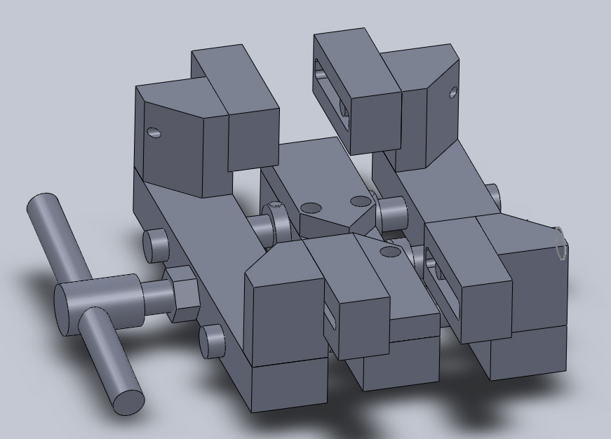
Clamp System
- 1 Fixed Block with 2 shaft holes and 1 threaded rod hole on a centerline; the Fixed Block is mounted onto the Baseplate with 4 holes.
- 2 Moving Blocks with 2 shaft holes and 1 threaded rod hole with welded nut.
- The shafts have 2 shaft collars each axially holding them on the Fixed Block.
- The threaded rod has 2 thrust washers and 2 shaft collars axially holding it on the Fixed Block.
- Clamp Jaws are attached to the inside face of the Moving Blocks to lower the minimum clampable workpiece width.
Clamp Threaded Rod and Shafts Positioning
- The workpiece must be secure during operation.
Therefore the cut must occur near the center of the clamping volume.
- The blade must not contact the Threaded Rod at any cut angle. The Threaded Rod is at the center of the clamping volume.
Therefore a space must exist between the blade bottom-out and Threaded Rod at all cut angles.
- We want the clamp volume to be as close to the Baseplate as possible for minimizing material usage and improving Fixed Block rigidity. Lower height of blade bottom-out permits lower working volume, hence allows the clamp volume to be designed closer to the Baseplate. Below the blade bottom-out plane must be a space, then the Threaded Rod.
Therefore the Threaded Rod must be mounted as close to the Baseplate as possible.
- The shafts must balance the Threaded Rod's driving force and the workpiece's reaction force such that the Threaded Rod and Moving Block do not bend.
Therefore the Shafts must be mounted between the middle of the Threaded Rod and the middle of the clamp volume's height.
Support System
- 2 Shaft Blocks radially support the ends of the Support Shaft.
- The Support Shaft is axially held by shaft collars on its outside ends.
- The Support Shaft has thrust washers on its inside ends.
- The Main Bar and Support Bar are mounted on the Support Shaft between the thrust washers.
- The Bridge Bars span the Main Bar and Support Bar to connect them and add rigidity.
Drive Assembly
- The Interface Plate allows mounting of the hydraulic motor.
- The Hydraulic Motor drives the Shaft Coupling with a setscrew and keyway connection.
- The Shaft Coupling transfers kinetic energy from the Hydraulic Motor into the Spindle.
- The Spindle is welded inside the Shaft Coupling and is threaded on its active end for nut fastening.
- The Inside Plate is welded to the active face of the Shaft Coupling and has a pinhole pattern for the Blade.
- The Outside Plate fits into the spindle and has a pinout pattern for the Blade.
- The Blade rotates on the spindle and its torque is ensured by the Outside Plate's pinout pattern going through the Blade's pinhole pattern into the Inside Plate's pinhole pattern.

