PowerCube6 Pump Mount: Difference between revisions
Jump to navigation
Jump to search
Tom Griffing (talk | contribs) (Created page with "==Engine Mounting Plates== * ¼” x 8” x 13.5” Plate * ¼” x 6” x 6” Plate * ¼” x 2” x 2” x 5” Angle (2 ea) ::Image:PumpMount.png ==Engine Mounts and Hy...") |
Tom Griffing (talk | contribs) |
||
| (One intermediate revision by the same user not shown) | |||
| Line 1: | Line 1: | ||
==Engine Mounting Plates== | ==Engine Mounting Plates== | ||
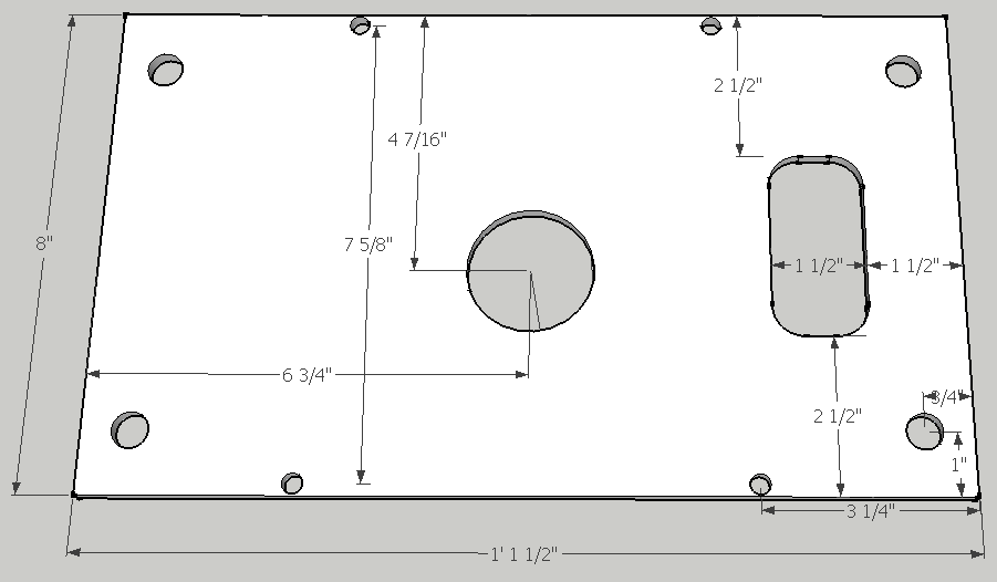
* ¼” x 8” x 13.5” Plate | * ¼” x 8” x 13.5” Plate | ||
::[[Image:EnginePlate.png]] | |||
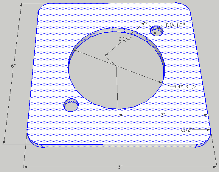
* ¼” x 6” x 6” Plate | * ¼” x 6” x 6” Plate | ||
::[[Image:PumpPlate.png]] | |||
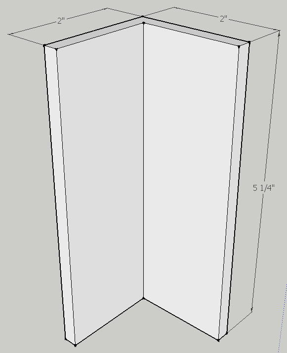
* ¼” x 2” x 2” x 5” Angle (2 ea) | * ¼” x 2” x 2” x 5” Angle (2 ea) | ||
::[[Image:PumpAngle.png]] | |||
==Engine / Pump Mount Assembly== | |||
==Engine | |||
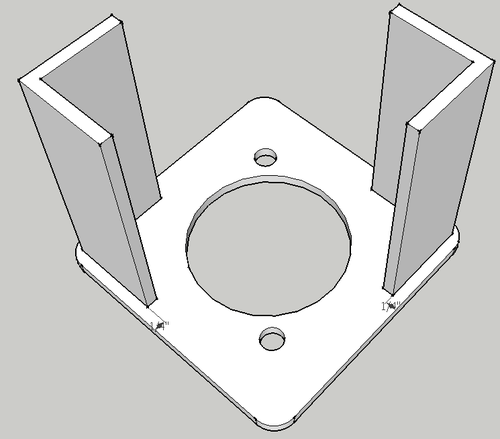
* | * Align the two 1/4" x 2" x 2" anglt iron pieces on the pump plate as shown below and weld securely. | ||
::[[Image: | ::[[Image:PumpAngleWeld.png|500px]] | ||
* | * Mount the engine to the engine plate using [4] 5/16” x 2” bolts and [4] rubber vibration mounts. | ||
* Slide the shaft coupling onto the engine shaft and secure the hex screw. | |||
* | * Mount the pump onto the pump plate and secure with [2] 7/16" x 1 1/2" bolts. | ||
* Slide the splined pump shaft into the shaft coupling so the angle touches the engine plate and is oriented as shown. | |||
See the following video for details: | |||
::{{YoutubePopup|DO6wbwOjWNA||powercube-window}} | ::{{YoutubePopup|DO6wbwOjWNA||powercube-window}} | ||
* Examine the engine shaft – it should be 2” long. If longer, cut the shaft to extend no more than 2” from the case. This length is necessary for the coupling. Put the larger keystock in the engine shaft and slide the shaft coupling on the engine shaft and tighten the allen screws to hold it in place. | * Examine the engine shaft – it should be 2” long. If longer, cut the shaft to extend no more than 2” from the case. This length is necessary for the coupling. Put the larger keystock in the engine shaft and slide the shaft coupling on the engine shaft and tighten the allen screws to hold it in place. | ||
Latest revision as of 04:29, 18 August 2012
Engine Mounting Plates
- ¼” x 8” x 13.5” Plate
- ¼” x 6” x 6” Plate
- ¼” x 2” x 2” x 5” Angle (2 ea)
Engine / Pump Mount Assembly
- Align the two 1/4" x 2" x 2" anglt iron pieces on the pump plate as shown below and weld securely.
- Mount the engine to the engine plate using [4] 5/16” x 2” bolts and [4] rubber vibration mounts.
- Slide the shaft coupling onto the engine shaft and secure the hex screw.
- Mount the pump onto the pump plate and secure with [2] 7/16" x 1 1/2" bolts.
- Slide the splined pump shaft into the shaft coupling so the angle touches the engine plate and is oriented as shown.
See the following video for details:
- Examine the engine shaft – it should be 2” long. If longer, cut the shaft to extend no more than 2” from the case. This length is necessary for the coupling. Put the larger keystock in the engine shaft and slide the shaft coupling on the engine shaft and tighten the allen screws to hold it in place.


