CEB Modeling: Difference between revisions
No edit summary |
|||
| (5 intermediate revisions by 3 users not shown) | |||
| Line 14: | Line 14: | ||
http://www.overstock.com/Auto-Parts/3-8-inch-Ratcheting-Torque-Wrench/3142342/product.html?SEC_IID=29607 | http://www.overstock.com/Auto-Parts/3-8-inch-Ratcheting-Torque-Wrench/3142342/product.html?SEC_IID=29607 | ||
==3D Models== | |||
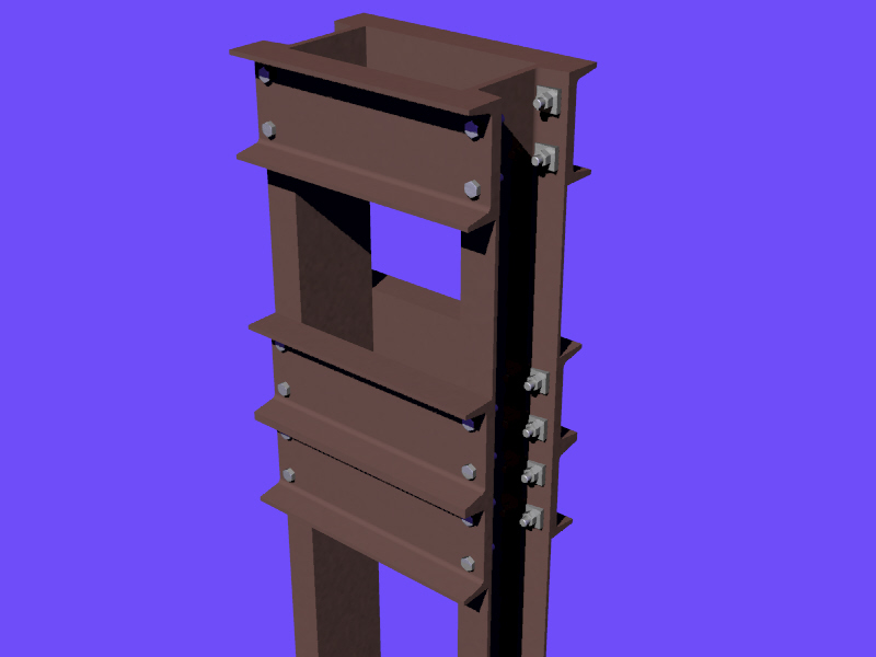
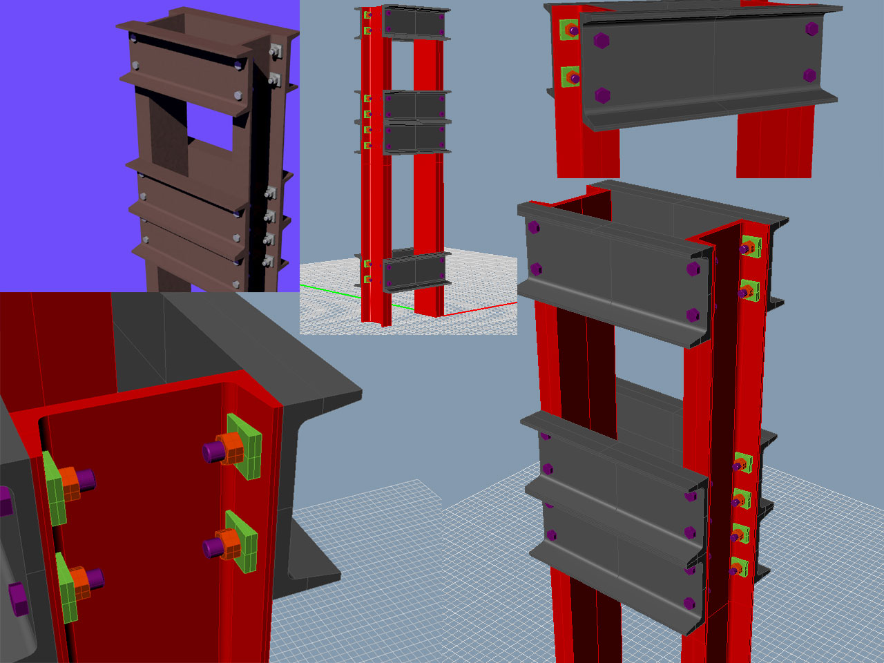
Starting to create the 3D model from previous sketches provided. We should take a look at using square washers on the back of the channels, they help to apply the forces evenly on the bolts and structure. | Starting to create the 3D model from previous sketches provided. We should take a look at using square washers on the back of the channels, they help to apply the forces evenly on the bolts and structure. | ||
| Line 19: | Line 21: | ||
*Where do I get these washers? Do they have ones that match the slope of the u-channel, or must I obtain them by cutting up another piece of u-channel? | *Where do I get these washers? Do they have ones that match the slope of the u-channel, or must I obtain them by cutting up another piece of u-channel? | ||
[[Image:CEB-Start.jpg | [[Image:CEB-Start.jpg|Start of the modeling]] | ||
[[Image:CEB-Start1.jpg|More views]] | |||
[[Image:Cylinder-Gladiator.jpg|See large image for part numbers]] | |||
[[Image:Hopper-Assy1.jpg|More views]] | |||
| Line 27: | Line 34: | ||
*The top part of chamber is u-channel because it requires the strength. The bottom doesn't require the strength - as it is only the beginning of the compression stroke. Moreover, it needs to be longer so that it encloses the entire compression plate assembly. | *The top part of chamber is u-channel because it requires the strength. The bottom doesn't require the strength - as it is only the beginning of the compression stroke. Moreover, it needs to be longer so that it encloses the entire compression plate assembly. | ||
Thanks again for the additional construction videos, I will be traveling the first couple of days this week for business. I will get back to the frame details later this week. The compression chamber and hopper make a lot more sense after looking at the additional construction information. I have a couple of ideas for the mounting pins for the cylinders that could make disassembly a little easier. I'll get sketches to you later this week. | |||
I am using Rhino3D for the modeling. I have just loaded version 4.0, so to make sure that no issues revolve arounf functionality, version 3.0 is still used for the rendering. | |||
More details on the Rhino program can be found here. www.rhino3d.com | |||
[[Category:CEB]] | |||
Latest revision as of 01:56, 6 February 2009
Introduction
This page is dedicated to visual and performance modeling of the Liberator, OSE's open source, high-performance CEB press.
Finite Element Analysis
Calculation Symmetry
Bolt Strength
Bolt torquing can be measured by a torque wrench:
3D Models
Starting to create the 3D model from previous sketches provided. We should take a look at using square washers on the back of the channels, they help to apply the forces evenly on the bolts and structure.
- Where do I get these washers? Do they have ones that match the slope of the u-channel, or must I obtain them by cutting up another piece of u-channel?
Marcin, I see from the video that you provided that you have modified the chamber to use a 1/4 plate on the side. What was your reasoning?
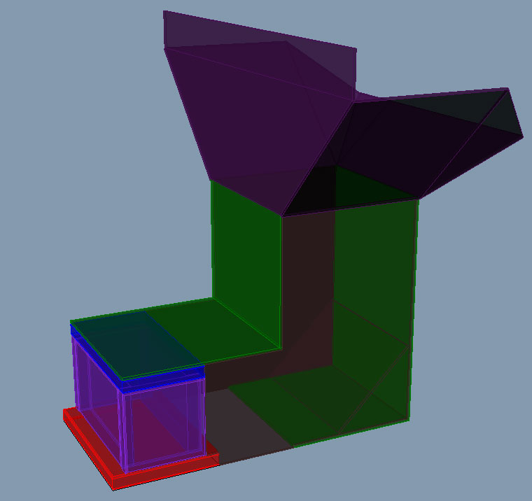
- The top part of chamber is u-channel because it requires the strength. The bottom doesn't require the strength - as it is only the beginning of the compression stroke. Moreover, it needs to be longer so that it encloses the entire compression plate assembly.
Thanks again for the additional construction videos, I will be traveling the first couple of days this week for business. I will get back to the frame details later this week. The compression chamber and hopper make a lot more sense after looking at the additional construction information. I have a couple of ideas for the mounting pins for the cylinders that could make disassembly a little easier. I'll get sketches to you later this week.
I am using Rhino3D for the modeling. I have just loaded version 4.0, so to make sure that no issues revolve arounf functionality, version 3.0 is still used for the rendering.
More details on the Rhino program can be found here. www.rhino3d.com


