CEB Press/Manufacturing Instructions/Arms - primary: Difference between revisions
Jump to navigation
Jump to search
(→Fabrication Steps: realized holes for attaching to main frame were too far apart.) |
No edit summary |
||
| (25 intermediate revisions by 4 users not shown) | |||
| Line 1: | Line 1: | ||
[[Image:Farmewitharms.jpg|thumb]] | [[Image:Farmewitharms.jpg|thumb]] | ||
=Part Information= | |||
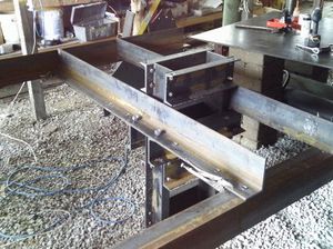
The primary arms attach the cylinder/frame assembly to the secondary arms, which support it. They also attach to the Brickholder Plate, the Dirt-Keeper Plate, the Controller Mount, and the Valve Mount. | |||
=Tools= | |||
*Hole punch with 3/4" die | |||
* | *Measuring Tape | ||
== | *Metal Marking Utensil | ||
=Materials= | |||
*[2] Steel Angle 4" A by 6" B, 1/2" Thickness, 72" Length | |||
=Steps= | |||
*Mark and punch holes as shown below. | |||
Left | Left | ||
[[Image:LeftPrimaryArm.png|700px]] | |||
Right | Right | ||
[[Image:RightPrimaryArm.png|700px]] | |||
[[ | |||
*Label arms as left and right from the perspective of an observer looking at the CEB Press from the ejection side. | |||
Latest revision as of 02:36, 23 December 2011
Part Information
The primary arms attach the cylinder/frame assembly to the secondary arms, which support it. They also attach to the Brickholder Plate, the Dirt-Keeper Plate, the Controller Mount, and the Valve Mount.
Tools
- Hole punch with 3/4" die
- Measuring Tape
- Metal Marking Utensil
Materials
- [2] Steel Angle 4" A by 6" B, 1/2" Thickness, 72" Length
Steps
- Mark and punch holes as shown below.
Left
Right
- Label arms as left and right from the perspective of an observer looking at the CEB Press from the ejection side.
