CEB Press/Manufacturing Instructions/Arms - primary: Difference between revisions

From Open Source Ecology
Jump to navigation Jump to search
No edit summary
 
(19 intermediate revisions by 4 users not shown)
Line 1: Line 1:
{{Template:CEB Press Manufacturing Instructions Navbox}}
[[Image:Farmewitharms.jpg|thumb]]
[[Image:Farmewitharms.jpg|thumb]]


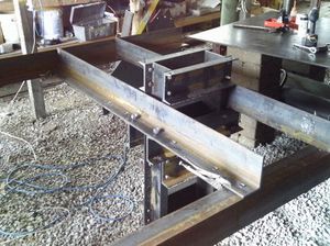
The primary arms attach the cylinder/frame assembly to the secondary arms, which support it. They also attach to the [[Brickholder plate]], the [[Dirt-keeper plate]], the [[Controller Mount]], and the [[Valve Mount]].
=Part Information=


== Tools Required ==
The primary arms attach the cylinder/frame assembly to the secondary arms, which support it. They also attach to the Brickholder Plate, the Dirt-Keeper Plate, the Controller Mount, and the Valve Mount.


Hole punch with 13/16" and 3/4" dies
=Tools=


== Materials Required ==
*Hole punch with 3/4" die


*2 pieces 72" long - 4"x6"x1/2" angle steel
*Measuring Tape


== Diagrams ==
*Metal Marking Utensil


Left
=Materials=


<html>
*[2] Steel Angle 4" A by 6" B, 1/2" Thickness, 72" Length
<iframe src="http://sketchup.google.com/3dwarehouse/mini?mid=4b3895a4daf1bff5b38804396e417a9b&etyp=im&width=400&height=300" frameborder="0" scrolling="no" marginheight="0" marginwidth="0" width="400" height="300"></iframe>
</html>


Right
=Steps=


<html>
*Mark and punch holes as shown below.
<iframe src="http://sketchup.google.com/3dwarehouse/mini?mid=f3f1afb53da762bcb38804396e417a9b&etyp=im&width=400&height=300" frameborder="0" scrolling="no" marginheight="0" marginwidth="0" width="400" height="300"></iframe>
</html>


shonda's print for the Super CEB
Left


[[File:MAIN_ARM_CONTROL_SIDE_WITH_DETAIL.jpg]]
[[Image:LeftPrimaryArm.png|700px]]
[[Image:beginningassembly.jpg|thumb|1400px]]
 
Right


== Fabrication Steps ==
[[Image:RightPrimaryArm.png|700px]]
There are two primary arms, one from each 6' (72”) piece of angle steel. The arms will not be identical, as arm B will have no holes punched on the 6” side whereas the other arm, arm A will need holes punched on the 6” side.
#On one piece, mark holes on the 4" side, all 1.25" away from the edge for:
#*Two total 3/4” diameter holes at 2” and 70.”
#*Six total 13/16” diameter holes at 27", 37", 39 3/4", 48 1/4", 51", and 63 1/2".
#Use this piece to mark the locations on the other side. They are to be mirrored, so make sure they aren't in the same exact orientation.
#Determine which one is arm A and which is arm B by looking at the diagrams. Label them.
#Punch the holes.


On arm A, punch the following holes on the 6” side of the angle iron, measured from the left, each centered 1 3/4” from the long edge:
*Label arms as left and right from the perspective of an observer looking at the CEB Press from the ejection side.
*Five total 13/16” diameter holes at 9”, 13”, 18”, 28”, and 30" inches.
*Also, torch the hole for adjusting the rollers at 45". Its shape is shown in the diagrams.
*Torch the roller adjustor hole in arm B, 45" from the right, so the holes will be at the same frame location.

Latest revision as of 02:36, 23 December 2011

Farmewitharms.jpg

Part Information

The primary arms attach the cylinder/frame assembly to the secondary arms, which support it. They also attach to the Brickholder Plate, the Dirt-Keeper Plate, the Controller Mount, and the Valve Mount.

Tools

  • Hole punch with 3/4" die
  • Measuring Tape
  • Metal Marking Utensil

Materials

  • [2] Steel Angle 4" A by 6" B, 1/2" Thickness, 72" Length

Steps

  • Mark and punch holes as shown below.

Left

File:LeftPrimaryArm.png

Right

File:RightPrimaryArm.png

  • Label arms as left and right from the perspective of an observer looking at the CEB Press from the ejection side.