CEB Press/Manufacturing Instructions/Arms - primary: Difference between revisions

From Open Source Ecology
Jump to navigation Jump to search
No edit summary
 
(18 intermediate revisions by 4 users not shown)
Line 1: Line 1:
{{Template:CEB Press Manufacturing Instructions Navbox}}
[[Image:Farmewitharms.jpg|thumb]]
[[Image:Farmewitharms.jpg|thumb]]


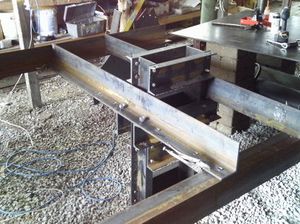
The primary arms attach the cylinder/frame assembly to the secondary arms, which support it. They also attach to the [[Brickholder plate]], the [[Dirt-keeper plate]], the [[Controller Mount]], and the [[Valve Mount]].
=Part Information=


== Tools Required ==
The primary arms attach the cylinder/frame assembly to the secondary arms, which support it. They also attach to the Brickholder Plate, the Dirt-Keeper Plate, the Controller Mount, and the Valve Mount.


Hole punch with 13/16" and 3/4" dies
=Tools=


== Materials Required ==
*Hole punch with 3/4" die


*2 pieces 72" long - 4"x6"x1/2" angle steel
*Measuring Tape


== Diagrams ==
*Metal Marking Utensil


Left
=Materials=


<html>
*[2] Steel Angle 4" A by 6" B, 1/2" Thickness, 72" Length
<iframe src="http://sketchup.google.com/3dwarehouse/mini?mid=4b3895a4daf1bff5b38804396e417a9b&etyp=im&width=400&height=300" frameborder="0" scrolling="no" marginheight="0" marginwidth="0" width="400" height="300"></iframe>
</html>


Right
=Steps=


<html>
*Mark and punch holes as shown below.
<iframe src="http://sketchup.google.com/3dwarehouse/mini?mid=f3f1afb53da762bcb38804396e417a9b&etyp=im&width=400&height=300" frameborder="0" scrolling="no" marginheight="0" marginwidth="0" width="400" height="300"></iframe>
</html>


shonda's print for the Super CEB
Left


[[File:MAIN_ARM_CONTROL_SIDE_WITH_DETAIL.jpg]]
[[Image:LeftPrimaryArm.png|700px]]
[[Image:beginningassembly.jpg|thumb|1400px]]
 
Right


== Fabrication Steps ==
[[Image:RightPrimaryArm.png|700px]]
There are two primary arms, one from each 6' (72”) piece of angle steel. The arms will not be identical, as arm B will have no holes punched on the 6” side whereas the other arm, arm A, will need holes punched on the 6” side. The holes for the grate supports will be torched in place.
#On one piece, mark holes on the 4" side, all 1.25" away from the edge for:
#*Two total 3/4” diameter holes at 2” and 70.”
#*Six total 13/16” diameter holes at 27", 37", 39 3/4", 48 1/4", 51", and 63 1/2".
#Use this piece to mark the locations on the other side. They are to be mirrored, so make sure they aren't in the same exact orientation.
#Determine which one is arm A and which is arm B by looking at the diagrams. Label them.
#Punch the holes.


On arm A, punch the following holes on the 6” side of the angle iron, measured from the left, each centered 1 3/4” from the long edge:
*Label arms as left and right from the perspective of an observer looking at the CEB Press from the ejection side.
*Five total 13/16” diameter holes at 9”, 13”, 18”, 28”, and 30" inches.
*Also, torch the hole for adjusting the rollers at 45". Its shape is shown in the diagrams.
*Torch the roller adjustor hole in arm B, 45" from the right, so the holes will be at the same frame location.

Latest revision as of 02:36, 23 December 2011

Farmewitharms.jpg

Part Information

The primary arms attach the cylinder/frame assembly to the secondary arms, which support it. They also attach to the Brickholder Plate, the Dirt-Keeper Plate, the Controller Mount, and the Valve Mount.

Tools

  • Hole punch with 3/4" die
  • Measuring Tape
  • Metal Marking Utensil

Materials

  • [2] Steel Angle 4" A by 6" B, 1/2" Thickness, 72" Length

Steps

  • Mark and punch holes as shown below.

Left

File:LeftPrimaryArm.png

Right

File:RightPrimaryArm.png

  • Label arms as left and right from the perspective of an observer looking at the CEB Press from the ejection side.