CEB Press/Manufacturing Instructions/Soil Shaker motor unit: Difference between revisions
Jump to navigation
Jump to search
No edit summary |
(→Steps) |
||
| (12 intermediate revisions by 2 users not shown) | |||
| Line 1: | Line 1: | ||
[[Image:shaker motor.jpg|thumb]] | |||
[[Image: | [[Image:Shakermotor.png|thumb]] | ||
=Tools= | |||
*Various Wrenches | *Various Wrenches | ||
*Crescent Wrench | *Crescent Wrench | ||
=Materials= | |||
Note: NPT means national pipe thread, and refers to the interior diameter of the hoses. NPTM means a male end, and NPTF means a female end. | |||
*Thread tape | *Thread tape | ||
*Shaker motor | |||
*1/2" NPT Needle Valve (1) | |||
*1/4"x12" NPTM Hydraulic hose (1) | |||
*1/2"x36" NPTM Hydraulic hoses (2) | |||
*SAE 4M to 1/4" NPTF Swivel (1) | |||
*1/2" NPT Hex Nipple (2) | |||
*1/2" NPTF Tee (1) | |||
*1/2" NPTM to 1/4" NPTF bushing | |||
=Diagrams= | |||
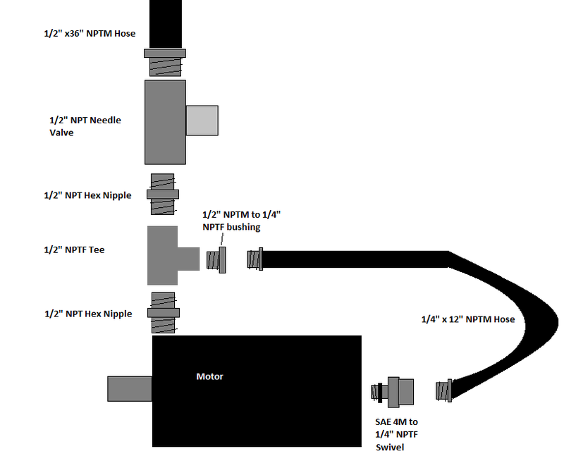
[[Image:shakerhyd.png|800px|The Shaker Motor hydraulics schematic]] | |||
=Steps= | |||
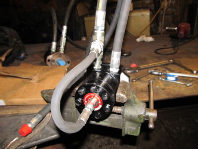
[[Image:shakerhydvise.jpg|thumb|400px|How to clamp the motor and where to put needle valve assembly. | |||
Note:the needle valve should be attatched to the tee in this photo.]] | |||
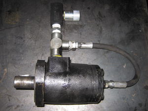
[[Image:shakerdone.jpg|thumb|400px|The finished shaker Note:the needle valve should be attatched to the tee in this photo.]] | |||
*Thread tape is necessary between each connection unless otherwise stated. | |||
*Always wrap thread tape clockwise when facing the threaded portion. | |||
*Always keep the end caps on hoses and fittings until you need to take them off. They need to stay protected inside. | *Always keep the end caps on hoses and fittings until you need to take them off. They need to stay protected inside. | ||
*Clamp the motor in a vise so that the side opposite the shaft is facing up. | |||
*Remove the plug and install the SAE 4 adapter. This connection (and any others with an o-ring in general) doesn't need thread tape. Remove from vise. | |||
*Your motor will probably have fluid in it, so take care that the fluid doesn't leak everywhere when you remove the plug. | |||
*Clamp the needle valve in the vise and tighten a 1/2" nipple into it. Remove from vise. | |||
*Clamp the Tee in the vise and tighten the other 1/2" nipple on one side of it then flip it over and tighten the needle valve/nipple to it. | |||
*Rotate the tee in the vise and tighten the bushing and then the 1/4" hose into it. Remove from vise. | |||
*Clamp the motor in the vise as shown in the photo. | |||
*Remove the 2 plugs for the ports. | |||
*Install the Tee/needle valve/ hose assembly in the left port when facing the SAE fitting. See photo. | |||
*Get it tight, but make sure the hose is facing the adapter so that you can get it to the SAE adapter. | |||
*Tighten the 1/4" hose to the SAE adapter. | |||
*Tighten one 36" hose into the needle valve, and the other into the other port. | |||
Latest revision as of 05:12, 23 December 2011
Tools
- Various Wrenches
- Crescent Wrench
Materials
Note: NPT means national pipe thread, and refers to the interior diameter of the hoses. NPTM means a male end, and NPTF means a female end.
- Thread tape
- Shaker motor
- 1/2" NPT Needle Valve (1)
- 1/4"x12" NPTM Hydraulic hose (1)
- 1/2"x36" NPTM Hydraulic hoses (2)
- SAE 4M to 1/4" NPTF Swivel (1)
- 1/2" NPT Hex Nipple (2)
- 1/2" NPTF Tee (1)
- 1/2" NPTM to 1/4" NPTF bushing
Diagrams
Steps
- Thread tape is necessary between each connection unless otherwise stated.
- Always wrap thread tape clockwise when facing the threaded portion.
- Always keep the end caps on hoses and fittings until you need to take them off. They need to stay protected inside.
- Clamp the motor in a vise so that the side opposite the shaft is facing up.
- Remove the plug and install the SAE 4 adapter. This connection (and any others with an o-ring in general) doesn't need thread tape. Remove from vise.
- Your motor will probably have fluid in it, so take care that the fluid doesn't leak everywhere when you remove the plug.
- Clamp the needle valve in the vise and tighten a 1/2" nipple into it. Remove from vise.
- Clamp the Tee in the vise and tighten the other 1/2" nipple on one side of it then flip it over and tighten the needle valve/nipple to it.
- Rotate the tee in the vise and tighten the bushing and then the 1/4" hose into it. Remove from vise.
- Clamp the motor in the vise as shown in the photo.
- Remove the 2 plugs for the ports.
- Install the Tee/needle valve/ hose assembly in the left port when facing the SAE fitting. See photo.
- Get it tight, but make sure the hose is facing the adapter so that you can get it to the SAE adapter.
- Tighten the 1/4" hose to the SAE adapter.
- Tighten one 36" hose into the needle valve, and the other into the other port.


