Tesla Turbine Design Discussion: Difference between revisions
Jump to navigation
Jump to search
| Line 19: | Line 19: | ||
== Inlet Port == | == Inlet Port == | ||
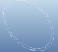
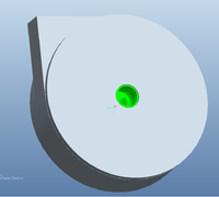
Using static orifice discs around the rotor has shown better results, both in simulation and testruns. The orifice profile in the pictures is just for illustration and not optimized, yet! | Using static orifice discs around the rotor has shown better results, both in simulation and testruns. The orifice profile in the pictures is just for illustration and not optimized, yet! | ||
<br> | |||
[[File:TeslaTurbine_MK4_7.jpg|200px]] | [[File:TeslaTurbine_MK4_7.jpg|200px]] | ||
[[File:TeslaTurbine_MK4_1.jpg|200px]] | [[File:TeslaTurbine_MK4_1.jpg|200px]] | ||
[[File:TeslaTurbine_MK4_2.jpg|200px]] | [[File:TeslaTurbine_MK4_2.jpg|200px]] | ||
Revision as of 19:28, 4 February 2014
Shaft
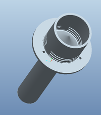
For optimizing flow, the exaust ports are integrated in the shaft. The convex cone should redirect the flow properly.
Discs
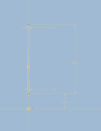
as the gap size depends on kinematic viscosity, entrance speed of the fluid and the relative disc diameter, its better to use a trapezoid profile for the discs. The laminar boundary thikness could be better used. Therefore friction should raise. This was inspired by the formula
<math>
x = 5 {\sqrt{v * l /u}}
x: gap Size
v: kinematic viscosity
l: relative disc diameter (Rmax - Rmin)
u: entrance Speed
</math>
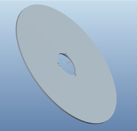
Inlet Port
Using static orifice discs around the rotor has shown better results, both in simulation and testruns. The orifice profile in the pictures is just for illustration and not optimized, yet!
