OSE Prusa: Difference between revisions
(→X Axis) |
|||
| Line 12: | Line 12: | ||
#Complete the 290mmx400mm horizontal frame by assembling a rectangle using the 290mm and 400mm extrusions and four corner brackets. | #Complete the 290mmx400mm horizontal frame by assembling a rectangle using the 290mm and 400mm extrusions and four corner brackets. | ||
#Place three corner brackets and one printer foot / printer foot bracket as feet for the horizontal frame. | #Place three corner brackets and one printer foot / printer foot bracket as feet for the horizontal frame. | ||
==X Axis== | ==X-Axis== | ||
#Attach the X-Axis Motor to the X-Axis Motor Mount. | #Attach the X-Axis Motor to the X-Axis Motor Mount. | ||
#Place three LM8UU Linear Bearings in the X-Axis Carriage Bracket and fasten them in place with small zip ties. | #Place three LM8UU Linear Bearings in the X-Axis Carriage Bracket and fasten them in place with small zip ties. | ||
#Attach the X-Axis Motor Mount and X-Axis Carriage Bracket to the X-Axis Motor with two 8mm smooth rods (300mm). | #Attach the X-Axis Motor Mount and X-Axis Carriage Bracket to the X-Axis Motor with two 8mm smooth rods (300mm). | ||
==Y-Axis== | ==Y-Axis== | ||
#Attach the Y-Axis Motor to the Y Axis Motor Mount and both onto the Horizontal Frame. | #Attach the Y-Axis Motor to the Y Axis Motor Mount and both onto the Horizontal Frame. | ||
Revision as of 19:27, 23 November 2019
OSE Prusa
Based on a Chinese version of the Prusa i3 printer, this represents a simple and low-part-count option for the Open Source Ecology product system.
Bill of Materials
Build Instructions
- Purchase and organize all parts from the Bill of Materials
Frame
- Make cuts in the 20mmx20mm aluminum extrusions: 400mmx3; 250mm*2; 320mm*2
- Slide T-Nuts for the Y Axis Idler, Motor Mount and Mounting Brackets onto the 250mm aluminum extrusions
- Slide T-Nuts for the Z-Axis Motor Mounts and Vertical Frame Mounts on two 400mm aluminum extrusions
- Complete the 290mmx400mm horizontal frame by assembling a rectangle using the 290mm and 400mm extrusions and four corner brackets.
- Place three corner brackets and one printer foot / printer foot bracket as feet for the horizontal frame.
X-Axis
- Attach the X-Axis Motor to the X-Axis Motor Mount.
- Place three LM8UU Linear Bearings in the X-Axis Carriage Bracket and fasten them in place with small zip ties.
- Attach the X-Axis Motor Mount and X-Axis Carriage Bracket to the X-Axis Motor with two 8mm smooth rods (300mm).
Y-Axis
- Attach the Y-Axis Motor to the Y Axis Motor Mount and both onto the Horizontal Frame.
- Attach the Y-Axis Pulley to the Y Axis Idler Using an M5 bolt and nut.
- Attach the Y-Axis Idler to the Horizontal Frame.
- Assemble two 320mm extrusions with one 400mm extrusion to form the vertical frame.
- Attach the Vertical Frame to the Horizontal Frame using two corner brackets and T-Nuts.
- Attach LM8UU bearings to each of the Bed Mounting Brackets using Zip Ties.
- Attach the Bed Mounting Brackets and Y-Axis Belt Holder to the aluminum bed plate.
- Slide two 8mm rods through the LM8UU bearings.
- Attach the Aluminum Bed Plate to the Horizontal Frame using the Y Axis Mounting Brackets. Make sure they are parallel and that the bed slides easily before tightening the screws.
- Attach the Y Axis Belt around the Y-Axis Motor, Idler and Belt Holder.
- Use small Zip Ties to hold the Y-Axis Belt in place with reasonable tension.
- Further tension the Y-Axis Belt with a Clothes Pin Spring.
Z Axis
- Attach the Z-Axis Top Left and Right Brackets to the front of the Vertical Frame Crossbar using T-Nuts.
- Attach the Z-Axis Motors to the Z-Axis Motor Mounts using M3 bolts.
- Attach the Z-Axis Couplers to the Z-Axis Acme Rods using the associated set-screws.
- Place the Z-Axis Couplers on the Z-Axis Motor Axles.
- Place the 8mm Smooth Rods in the related holes on the Z-Axis Motor Mounts.
- Place the Brass Nuts of X-Axis on the Z-Axis by turning the Z-Axis Acme Rods.
- Place the Z-Axis Smooth Rods in the related holes on the Top Left and Right Brackets.
- Tighten the Top Left and Right Brackets when you have made the Z-Axis Vertical and ensured that the X-Axis may move smoothly up and down.
Extruder
- Attach the Aluminum Extruder Block to the lower two holes of the Extruder Motor using M3 screws.
- Attach the Extruder Tube through the 6mm threaded hole of the Aluminum Extruder Block.
- Wind two 6mm nuts up the Extruder Tube to make sure that it stays in place. The top of the Extruder Tube should be even with the top of the Aluminum Extruder Block.
- Attach the Aluminum Heater Block and Brass Nozzle to the Extruder Tube.
Part Library
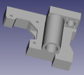
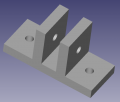
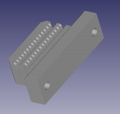
Here are the parts for the printer: (Nov. 23, 2019 - Note that the Y Belt Holder still needs to be drawn up in FreeCAD; we are still working on some minor edits to some of the parts - for the moment, we are drilling some holes in them for example)
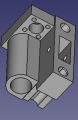
OSE Prusa X Axis Idler - FreeCAD -File:OSEPrusaXAxisIdler.FCStd
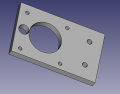
OSE Prusa X Axis Motor Mount - FreeCAD -File:OSEPrusaXAxisMotorMount.FCStd
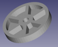
OSE Prusa Y Axis Idler - FreeCAD -File:OSEPrusaYAxisIdler.FCStd
OSE Prusa Y Belt Holder - FreeCAD -File:OSEPrusaYBeltHolder.FCStd
OSE Prusa Z Axis Motor Mount - FreeCAD -File:OSEPrusaZAxisMotorMount.FCStd
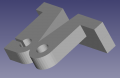
OSE Prusa Top Left Bracket - FreeCAD -File:OSEPrusaZAxisTopBracketLR.FCStd
OSE Prusa Top Right Bracket - FreeCAD -File:OSEPrusaZAxisTopBracketLR.FCStd
OSE Prusa Printer Foot - FreeCAD -File:OSEPrusaPrinterFoot.FCStd
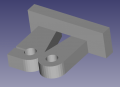
OSE Prusa Bed Bracket - FreeCAD -File:OSEPrusaBedBracket.FCStd


Extruder
This printer makes use of the OSE D3D Simple Extruder