CEB Press/Research Development/Hydraulic Design: Difference between revisions
(Created page with "= Hydraulic System Design of CEB = == Overview == The CEB contains three hydraulic circuits each operating a single actuator * '''Main Cylinder''', which compresses the earth<br>...") |
mNo edit summary |
||
| Line 33: | Line 33: | ||
* The case drain connection is unnecessary, as the motor has internal check valves which route case drain to whichever main port is at lower pressure. | * The case drain connection is unnecessary, as the motor has internal check valves which route case drain to whichever main port is at lower pressure. | ||
* Placing the needle valve in the return line causes the return pressure to be high during operation, which is stressful to the shaft seal. Consider moving the needle valve to the inlet side of the motor. | * Placing the needle valve in the return line causes the return pressure to be high during operation, which is stressful to the shaft seal. Consider moving the needle valve to the inlet side of the motor. | ||
[[Category:CEB]] | |||
[[Category:Hydrualics]] | |||
Revision as of 20:35, 27 December 2011
Hydraulic System Design of CEB
Overview
The CEB contains three hydraulic circuits each operating a single actuator
- Main Cylinder, which compresses the earth
This circuit is controlled by a 4-way solenoid valve which can raise, lower, or hold the cylinder in position, based on whether the A coil, B coil, or neither coil is energized. - Secondary Cylinder, which operates the drawer
This circuit is controlled by a 4-way solenoid valve which can retract, advance, or hold the cylinder in position, based on whether the A coil, B coil, or neither coil is energized. - Shaker Motor, which vibrates the hopper
This circuit is controlled by a 4-way solenoid valve, however only the A coil is used in this design; when energized the motor rotates.
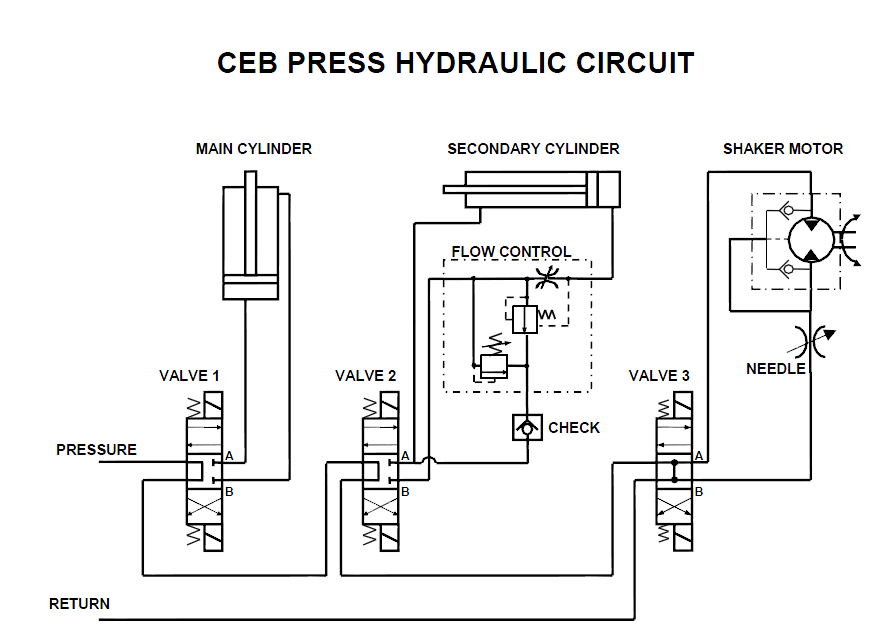
The circuits are arranged in an open-center, series configuration. Only one circuit is activated at a time. When no circuits are active, the hydraulic fluid flows freely through the three "open centers" of the valves and returns to the power unit.
Circuit Diagram
(Source file: File:CEB Hydraulic.ppt)
Circuit Description
Main Cylinder Circuit
The A and B ports of the 4-way valve are routed directly to the bottom and top ports of the cylinder.
Secondary Cylinder Circuit
The secondary cylinder circuit includes a pressure-compensated flow control valve which limits the advance speed of the drawer. When valve port B is pressurized (cylinder advance), fluid flows through the flow control valve to the cylinder at the set flow rate, while excess fluid passes through the check valve and returns to the power unit.
When valve port A is pressurized (cylinder retract), fluid flows directly to the front port of the cylinder. Fluid returns from the back port of the cylinder through the restriction in the flow control valve (not pressure compensated, so higher flow?) to the power unit.
The flow control valve incorporates an internal relief valve which limits the force applied on the advance stroke.
Shaker Motor Circuit
Unlike the cylinder circuits, this is a unidirectional circuit. When valve port A is pressurized, fluid flows through the motor and returns through the needle valve, which sets the flow rate and therefore the rpm of the motor.
Note that, unlike the cylinder circuits, this circuit uses a full-open-center valve which allows the motor to freewheel after the valve is de-energized; this limits pressure surges which might otherwise occur.
The motor case drain port is tee'd into the return line going to valve port B.
Design comments:
- The case drain connection is unnecessary, as the motor has internal check valves which route case drain to whichever main port is at lower pressure.
- Placing the needle valve in the return line causes the return pressure to be high during operation, which is stressful to the shaft seal. Consider moving the needle valve to the inlet side of the motor.
