CNCCMV2: Difference between revisions
| Line 238: | Line 238: | ||
[http://opensourceecology.org/wiki/GRBL Get GRBL] | [http://opensourceecology.org/wiki/GRBL Get GRBL] | ||
[http://opensourceecology.org/wiki/Gctrl Get Gctrl] | |||
=Getting Processing= | =Getting Processing= | ||
Revision as of 04:20, 30 March 2012
Action Plan
- Conceptual Design
- Specific Design
- Sourcing
- Manufacturing
- Testing
- Documentation During All of the Above
Design Rationale
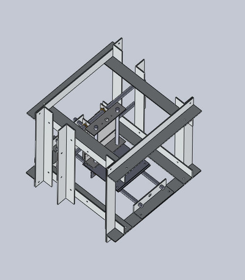
CAD Assembly: CNCube (In Progress)
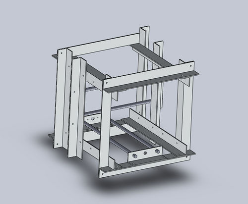
CAD Assembly: XY Frame
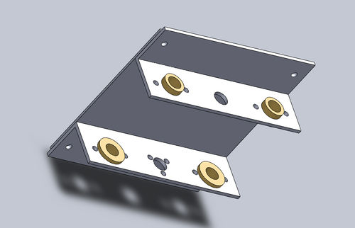
CAD Assembly: Platform
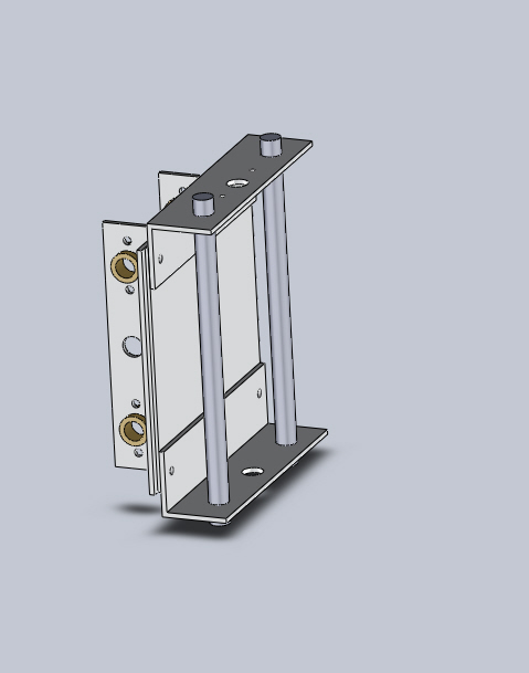
CAD Assembly: Z Frame
Connexions Modules
How to Use the CNC Circuit Mill
How to Design a CNC Circuit Mill
Making the Arduino IDE Work on Linux
Key Performance Specifications
- X Axis Travel Range = 20cm
- Y Axis Travel Range = 20cm
- Z Axis Travel Range = 5cm
- Step Motor Torque at 12VDC = 3.2kg-cm
- Spindle Max Rotation Speed = 22600rpm no-load
- Spindle Motor Torque at 24VDC = 88.5g-cm at max efficiency
- Workpiece Holding Mechanism = Linear Bolt and Tensioning Nut
- For Prototype II, define goals based on study of industry standards. Include desired precision + accuracy + speed.
- Minimum step size for each axis plus variance
- Repeatability of motion (drift) (determined by going to certain locations a large number of times)
- Minimum spacing between traces (determined by minimum allowable size of bit + precision)
- Minimum trace size possible
- Goal: repeatability is as good as step size - ie, all inaccuracy is negligible compared to step size, and zero backlash at all practical milling speeds.
- Define practical milling speed range based on substrate
Key Design Specifications
- Step Motor Axis Drive
- Rotary-to-Linear Motion Converting Stainless Steel Leadscrew and Wear-compensating Leadscrew Nut
- Anti-friction Bronze Sleeve Bearings
- Precision Stainless Steel Axis-Supporting Shafts
- Versatile Holding Platform with Magnets
- Brushed DC Motor Spindle Drive
- Precision Stainless Steel Spindle Shaft
- Computer to Microcontroller to Stepper Driver Electronics Pathway
- Gcode Streamer to Gcode Interpreter Software Pathway
Cost
- Cost values in USD. In practice, some items must be purchased in greater quantity than necessary; the following values are equalized to the correct quantities. List excludes tools and shipping.
- Cube Frame Metal =
- Axes Structure Metal =
- Metal Shafts = 124
- Leadscrews and Leadscrew Nuts = 240
- Bearings = 65
- Fasteners = 70
- Control and Drive Electronics = 130
- Power Supply = 35
- Software = Open Source
- Total =
Sourcing
- Spreadsheet File
LINK HERE
- Prototyping Spreadsheet
- To edit or download the spreadsheet, click on the following link.
https://docs.google.com/spreadsheet/ccc?key=0AlpsBarfpPkzdFk5aDY3dHM0eEhfZHNkWVppdV9EelE
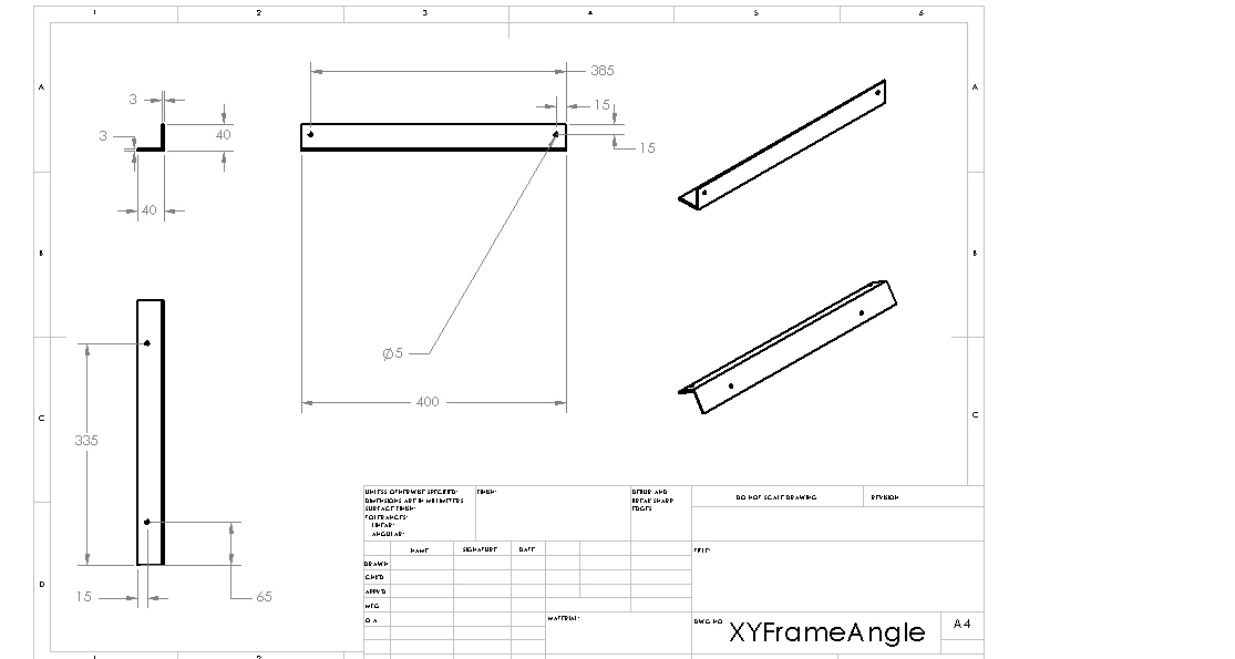
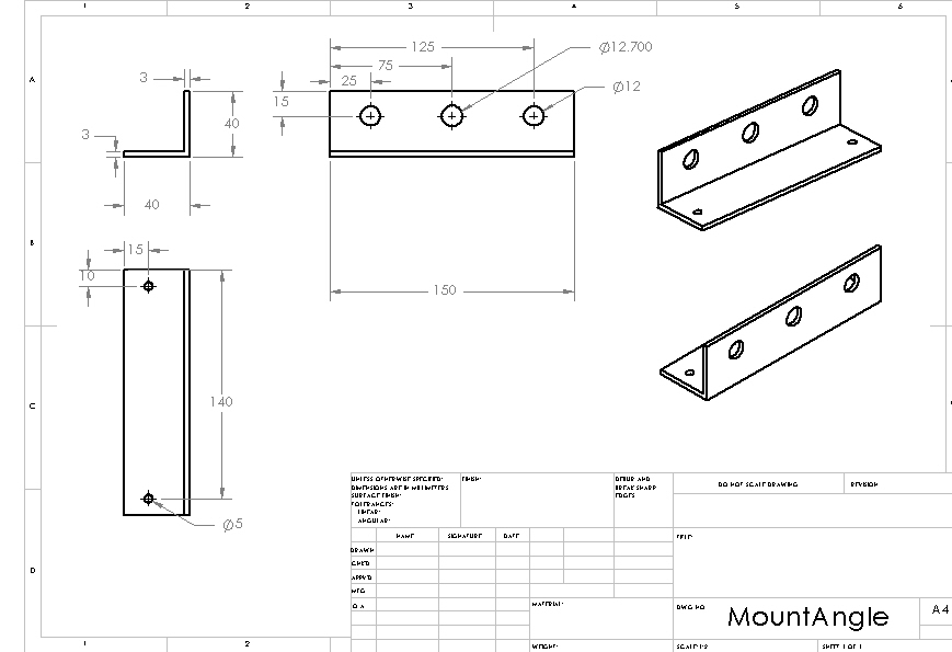
Structure: XY Frame Angle
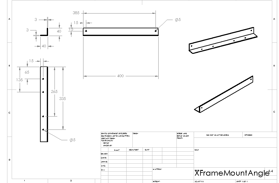
Structure: X Frame Mount Angle
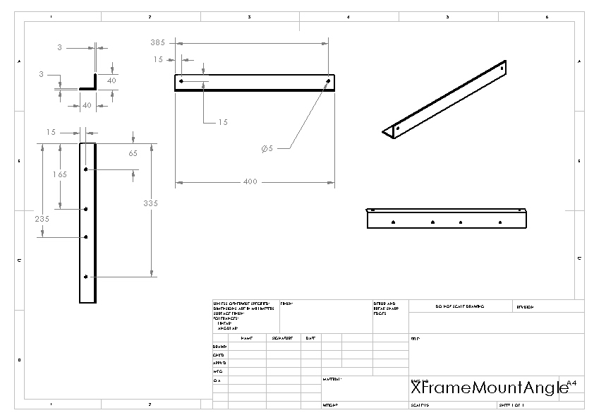
Structure: XY Frame Mount Angle
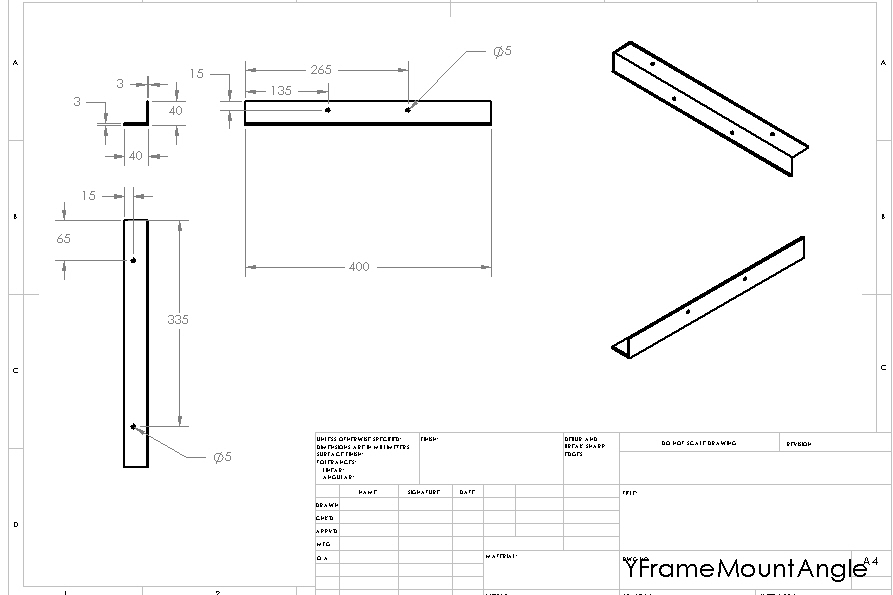
Structure: Y Frame Mount Angle
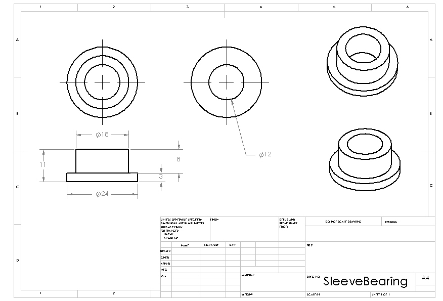
Structure: Sleeve Bearing
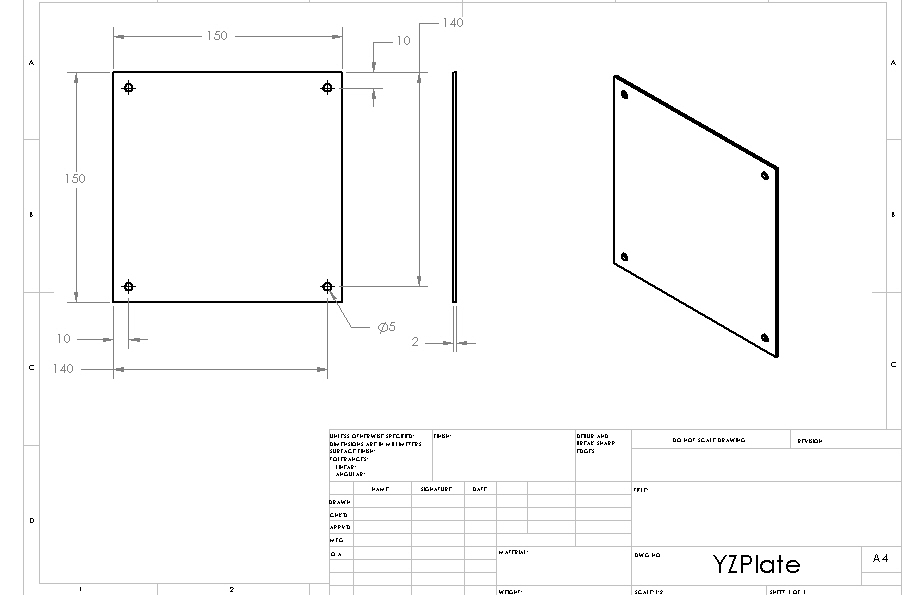
Structure: YZ Plate
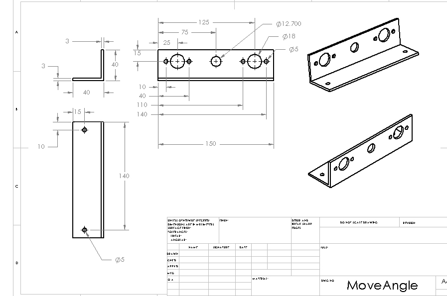
Structure: Move Angle
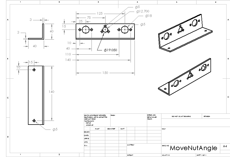
Structure: Move Nut Angle
Structure: Mount Angle
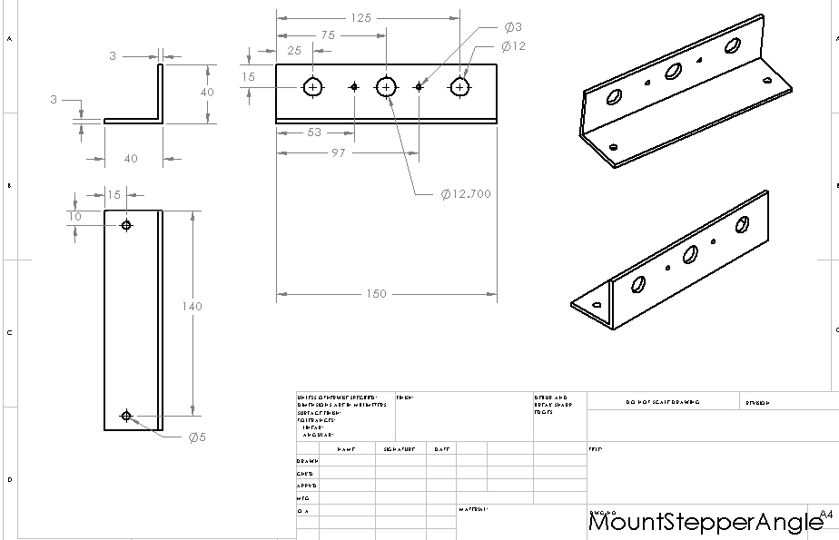
Structure: Mount Stepper Angle
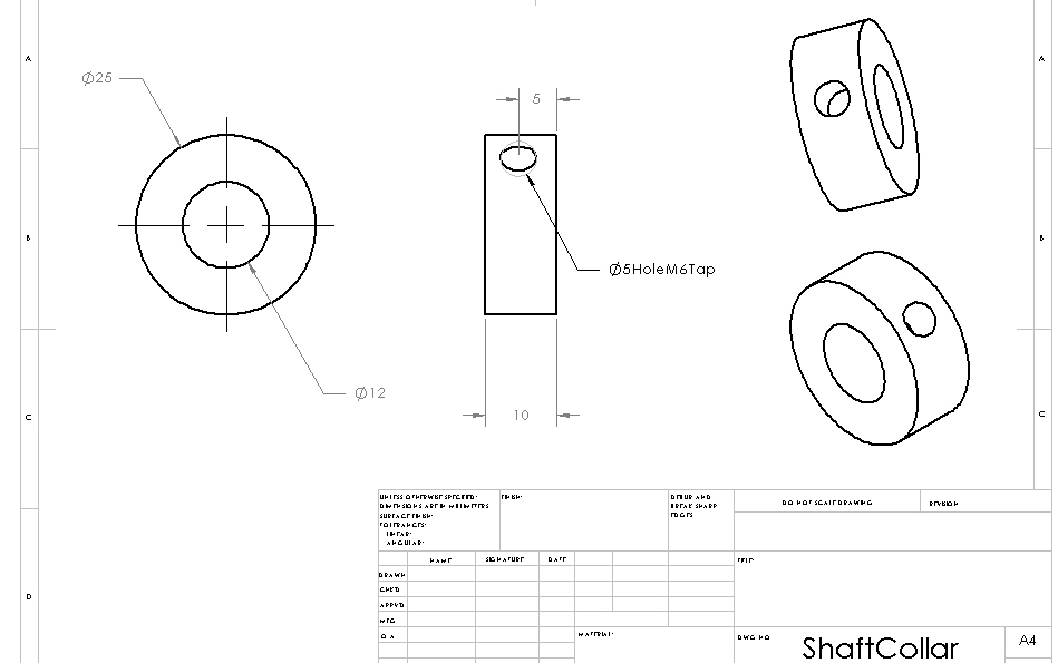
Structure: Shaft Collar
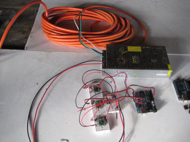
Electronics
Soldering Stepper Driver Pins
- Insert the short end of the male headers into the stepper driver board from the bottom, then pressfit the headers into the small breadboard for holding.
- Apply flux to all header connections
- Apply solder to the tip of the soldering iron
- Solder header connections at opposite corners of the stepper driver board for stability, reapplying solder to and cleaning the soldering iron tip as necessary; repeat for the remaining header connections.
Soldering Connectors
Wiring
Software
Ubuntu 10.04 LTS 32-Bit
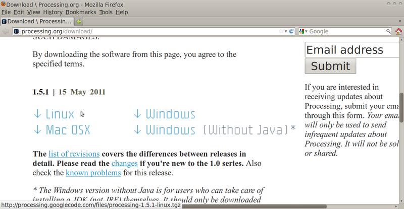
Getting Processing
- Go to this webpage:
http://processing.org/download/
- Download the latest version of Processing to a directory of your choosing
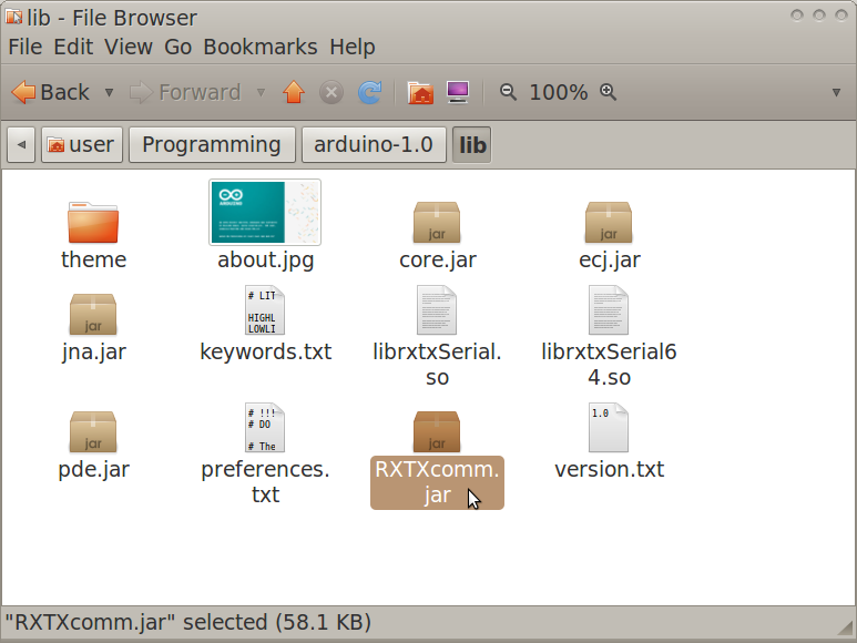
Moving RXTX files
- Navigate to the Arduino IDE folder>lib.
- Copy RXTXcomm.jar
- Navigate to the Processing folder>modes>java>libraries>serial>library
- Paste RXTXcomm.jar, replacing the existing version
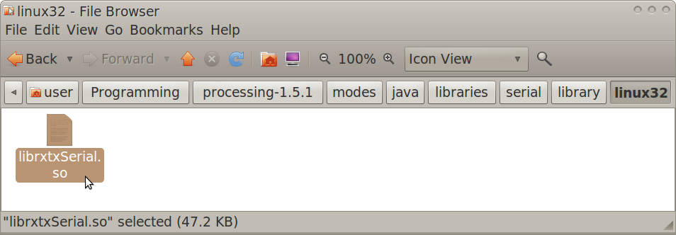
- Navigate to the Arduino IDE folder>lib
- Copy librxtxSerial.so
- Navigate to the Processing folder>modes>java>libraries>serial>library>Linux32
- Paste librxtxSerial.so, replacing the existing version
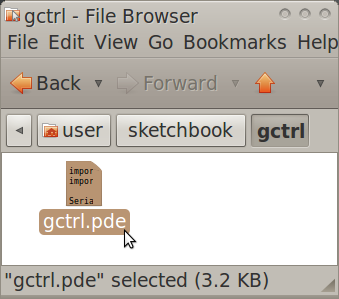
Modifying Gctrl
- Open the Gctrl folder
- Open gctrl.pde in gedit
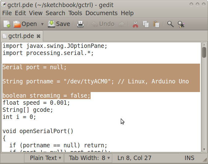
- Change a part of the code as annotated in the following:
Serial port = null; //change starts
String portname = "/dev/ttyACM0"; // Linux, Arduino Uno
//change ends
boolean streaming = false;
Modifying GRBL Files
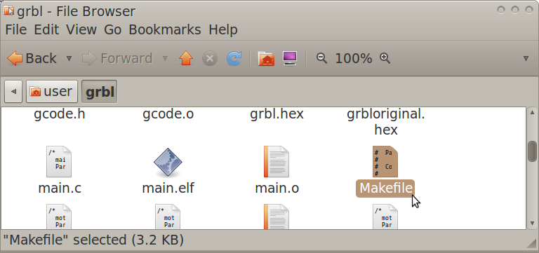
- Navigate to the GRBL folder
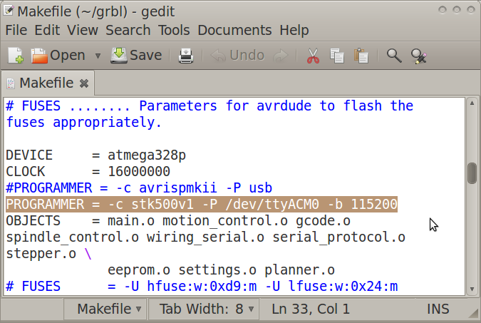
- Open "Makefile" in gedit
- Edit the PROGRAMMER line as:
PROGRAMMER = -c stk500v1 -P /dev/ttyACM0 -b 115200
Flashing GRBL
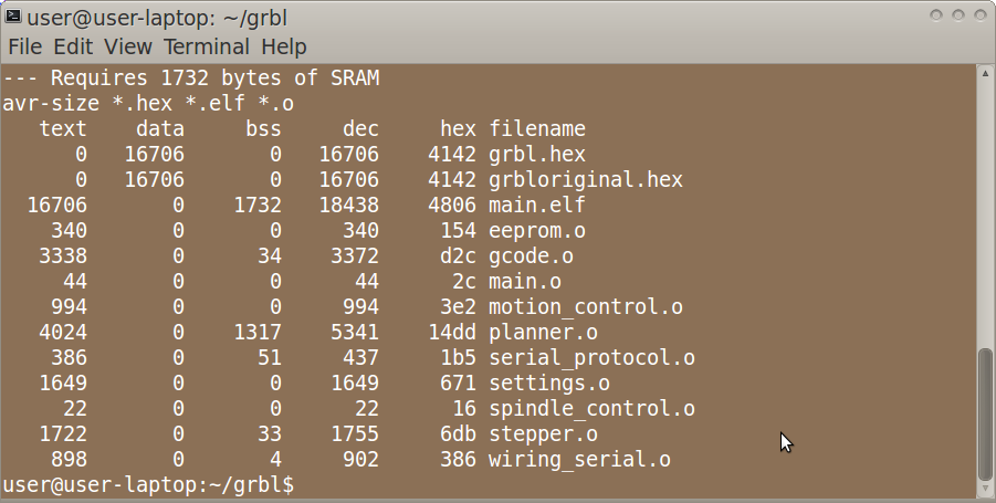
- Open Terminal and navigate to the GRBL folder (ex. by using the "ls" and "cd" commands)
- In Terminal, type:
make clean
- In Terminal, type:
make
- Connect the Arduino Uno to the computer via USB cable
- In Terminal, type:
make flash
- Disconnect the Arduino Uno
Running Gctrl
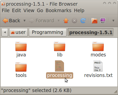
- Navigate to the Processing folder
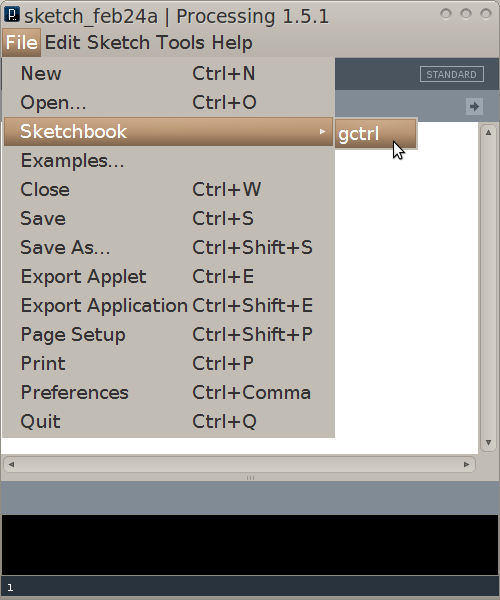
- Open and run Processing, setting the sketchbook folder as the folder in which the gctrl folder exists
- In Processing, open gctrl using File>Sketchbook>
- Connect the Arduino Uno to the computer via USB cable
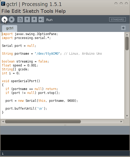
- In Processing, run gctrl using Sketch>Run
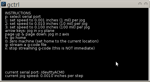
- Now the Gctrl GUI window should pop up
- Note: For certain functions of gctrl, press and hold down the key for the popup windows to populate.
Determining GRBL Configuration Changes Required
- Go to the following webpage:
http://dank.bengler.no/-/page/show/5474_configuringgrbl?ref=mst
Modifying GRBL Settings
- Navigate to the Arduino IDE folder
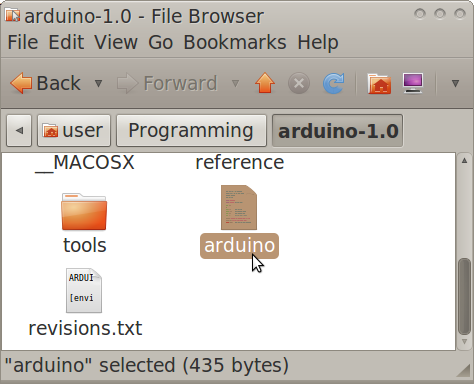
- Double-click "Arduino" then click "run" in the popup window
- Note: you may want to create a quick launcher for the Arduino IDE
- Connect the Arduino Uno to the computer via USB cable
- In Arduino IDE, open Tools>Serial Monitor
- Note: the Serial Monitor window should pop up and you should see the following:
Grbl 0.6b
'$' to dump current settings
- In the Serial Monitor, change the left drop-down setting to the following:
Both NL & CR
- In the Serial Monitor, type the following in the command line:
$
- Note: you should now see the following:
$0 = 157.480 (steps/mm x)
$1 = 157.480 (steps/mm y)
$2 = 157.480 (steps/mm z)
$3 = 10 (microseconds step pulse)
$4 = 500.0 (mm/min default feed rate)
$5 = 600.0 (mm/min default seek rate)
$6 = 0.100 (mm/arc segment)
$7 = 0 (step port invert mask. binary = 0)
$8 = 25.0 (acceleration in mm/sec^2)
$9 = 225.0 (max instant cornering speed change in delta mm/min)
'$x=value' to set parameter or just '$' to dump current settings
- In the Serial Monitor, type commands as necessary in the following format, where "X" and "Y" are numbers:
$X = Y
Design Modifications
Modularity
- Different step motors and drive mechanisms can be mounted onto the axis support angles via mounting holes
- Different frames can be used, provided they have precise mounting holes for the axis support angles
- Different holding platforms can be used, provided they have mounting holes for the X axis moving angles
- Different spindle setups can be used, provided they have mounting holes for the Z axis moving angles
- Different stepper driver boards and power supplies can be used, provided they have compatible performance specifications within the electronics system
Scaling
- Scaling mainly consists of changing the size of the frame (to affect travel ranges) and the type of step motors (to affect travel rates)
- Other discrete components such as fasteners, leadscrews, and shafts need only be scaled if necessary for functionality or certain desired performance specifications
- The travel range calculation for the X axis:
(X Travel Range) = (Distance Between 2 Parallel Frame Angles Along Horizontal Plane) - (Length of Platform Along Axis)
- The travel range calculation for the Y axis:
(Y Travel Range) = (Distance Between 2 Parallel Frame Angles Along Vertical Plane) - (Length of Z Support Angles Along Axis)
Usage
- Circuit Schematic to Gcode File Toolchain
- See following link for list of electronic design suites:
http://en.wikipedia.org/wiki/Comparison_of_EDA_software
- PCB-Gcode Optimizer
http://cnc.goodbits.net/wiki/index.php5/Pcb-gcode_optimizer
http://www.millpcbs.com/index.php?option=com_content&view=article&id=10&Itemid=44
Maintenance
Distributive Enterprise
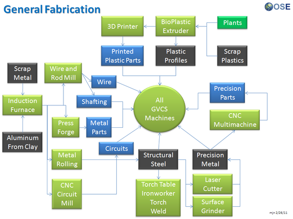
GVCS Product Ecology
Uses
- Induction Furnace - Steel
- Aluminum Extractor - Aluminum
- Metal Roller - Fasteners, Metal Angles, and Flats
- Rod and Wire Mill - Wires, Shafts
- CNC Multimachine - Bearings, Leadscrews, Leadscrew Nuts
- Motors - XYZ Movement
- CNC Circuit Mill - Control Circuit Boards
- Universal Power Supply - Power
Creates
- Milled Circuit Boards
See Product Ecologies for more information.
