Cold Saw/Understand2: Difference between revisions
(Created page with "=Starting the Design with the Right Focus= How the blade will be rotated and how the material will be held are the 2 major considerations. Following that, how to combine the ro...") |
|||
| Line 16: | Line 16: | ||
=Direct Drive= | =Direct Drive= | ||
[[Image: ColdSawV1HydDirDrv.png]] | |||
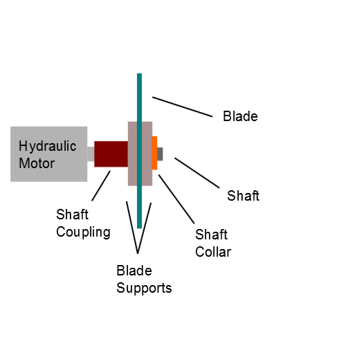
Going from left to right, the hydraulic motor has a shaft that rotates when hydraulic flow at a high enough pressure is applied to the hydraulic motor. Typically, a hydraulic motor has 3 ports (connection holes); 2 ports are used for input/output interchangeably depending on what direction the shaft should rotate; 1 port is used for the case drain, which transfers leaks in the hydraulic motor back into the hydraulic fluid reservoir (a hydraulic fluid container that is constantly poured into and pumped from). | |||
The hydraulic motor shaft is inserted into a shaft coupling and held by a setscrew which contacts the shaft surface and applies tension so that pulling the coupling out becomes difficult. | |||
A short shaft (not from the hydraulic motor) is inserted at the other end of the shaft coupling. This time, the short shaft is held to the shaft coupling by a bolt that inserts into a hole through one wall of the shaft coupling, through the entire short shaft, then through the other wall of the shaft coupling, at which point a nut can be fastened to the bolt to keep it in place. | |||
A large diameter, thin cylinder with a center hole is inserted into the short shaft, pressed tight and flat against the end of the shaft coupling, then welded to the shaft coupling. The thin cylinder also has a hole pattern on its large face that will be used to transfer large amounts of kinetic energy into the blade. Let's call this cylinder the "Blade Support" because it is a thin, large diameter part that the blade will rely on for rigidity and torque transmission. | |||
The blade now is inserted into the short shaft and pressed against the Blade Support | |||
Revision as of 19:11, 22 June 2012
Starting the Design with the Right Focus
How the blade will be rotated and how the material will be held are the 2 major considerations.
Following that, how to combine the rotation and holding mechanism into a single assembly while allowing the blade to move into and swivel at an angle to the material.
Rotating the Blade
Cold Saw rotation must let the material be chipped away. The rotation speed must be low so as to avoid producing dust. The torque must be high so as to ensure a consistent cutting process without stalling (the rotation stopping because not enough power was transmitted to the blade teeth to chip away the next layer of material).
Conventionally, Cold Saws use an AC motor (alternating current) that rotates at extremely high speeds with low torque. A multi-stage gearbox (multi-stage means a lot of gear reduction steps) is typically used to change the kinetic power output into low speed and high torque. Controlling the speed of an AC motor at a constant torque involves relatively complex electronics.
Hydraulic motors rotate at low speeds with exceptionally high torque; as such, no gearbox is required. Controlling the speed of a hydraulic motor at a constant torque involves a simple hydraulic flow splitter.
The Cold Saw's blade rotation will be powered by a hydraulic motor because hydraulic motors require no gear reduction and are simpler to control at constant torque than AC motors.
Direct Drive
Going from left to right, the hydraulic motor has a shaft that rotates when hydraulic flow at a high enough pressure is applied to the hydraulic motor. Typically, a hydraulic motor has 3 ports (connection holes); 2 ports are used for input/output interchangeably depending on what direction the shaft should rotate; 1 port is used for the case drain, which transfers leaks in the hydraulic motor back into the hydraulic fluid reservoir (a hydraulic fluid container that is constantly poured into and pumped from).
The hydraulic motor shaft is inserted into a shaft coupling and held by a setscrew which contacts the shaft surface and applies tension so that pulling the coupling out becomes difficult.
A short shaft (not from the hydraulic motor) is inserted at the other end of the shaft coupling. This time, the short shaft is held to the shaft coupling by a bolt that inserts into a hole through one wall of the shaft coupling, through the entire short shaft, then through the other wall of the shaft coupling, at which point a nut can be fastened to the bolt to keep it in place.
A large diameter, thin cylinder with a center hole is inserted into the short shaft, pressed tight and flat against the end of the shaft coupling, then welded to the shaft coupling. The thin cylinder also has a hole pattern on its large face that will be used to transfer large amounts of kinetic energy into the blade. Let's call this cylinder the "Blade Support" because it is a thin, large diameter part that the blade will rely on for rigidity and torque transmission.
The blade now is inserted into the short shaft and pressed against the Blade Support
