Compressed Air Water Pump: Difference between revisions
Jump to navigation
Jump to search
(→BOM) |
|||
| Line 17: | Line 17: | ||
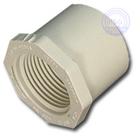
*2" Spigot x 3/4" Fips [http://www.plumbingsupply.com/pvc.html#plug] [[Image:plug.jpg|thumb]] | *2" Spigot x 3/4" Fips [http://www.plumbingsupply.com/pvc.html#plug] [[Image:plug.jpg|thumb]] | ||
*3/4" male thread coupling | *3/4" male thread coupling | ||
*3/4" | *[http://www.lowes.com/lowes/lkn?action=productDetail&productId=61252-34146-M31SL&lpage=none 3/4" brass check valve] | ||
*2 x 3/4" male threaded PVC plugs | *2 x 3/4" male threaded PVC plugs | ||
*2' x 3/4" PVC pipe | *2' x 3/4" PVC pipe | ||
Revision as of 18:30, 8 June 2009
Research
http://www.hydromissions.com/products.htm http://www.hydromissions.com/slapshotconstruction.pdf
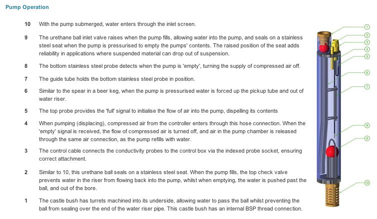
From http://www.airwellpumps.com/HowDoesItWork.aspx :
Design 1
BOM
- 2' x 2" PVC pipe
- 2" flat PVC cap
- 2" Spigot x 3/4" Fips [1]
- 3/4" male thread coupling
- 3/4" brass check valve
- 2 x 3/4" male threaded PVC plugs
- 2' x 3/4" PVC pipe
- 2 x 3/4" hoses long enough to go down the well
Construction
- Ream out one 3/4" male threaded PVC plug with a 3/4" hole for the 2' x 3/4" pipe and attach them.
- Drill two 5/8" holes in the flat PVC cap and tap them to 3/4" for the air in and water out 3/4" male threaded PVC plugs. Use plumbers tape and attach the plugs. Glue the PVC cap to the 2' x 2" pipe.
- Remove the spring of the metal check valve like in the hydromissions slapshot instructions.
- Glue the 2" to 3/4" plug to the other end of the 2' x 2" pipe, attach the 3/4" male threaded coupler and the 3/4" check valve.
- Attach the hoses to the plugs with plumbers tape and clamps and test the pump.

