CNC Circuit Mill: Difference between revisions
(Created page with 'From Christian: Image:christianrouter1.jpg Image:christianrouter2.jpg Image:christianrouter3.jpg Image:christianrouter4.jpg Image:christianrouter5.jpg [[Imag…') |
No edit summary |
||
| Line 1: | Line 1: | ||
From Christian: | From Christian Starkjohann: | ||
=Images= | |||
[[Image:christianrouter1.jpg]] | [[Image:christianrouter1.jpg]] | ||
[[Image:christianrouter2.jpg]] | [[Image:christianrouter2.jpg]] | ||
| Line 8: | Line 8: | ||
[[Image:christianrouter6.jpg]] | [[Image:christianrouter6.jpg]] | ||
=Description= | |||
The machine can move at ca. 15 to 20 mm/s, but for milling PCBs, I use only ca. 5 mm/s. You can compute how long it takes to mill a PCB from that. If you like, I can mail you the control software, this software has an emulation mode where you can find out how long a particular sequence of Gcode commands takes. | |||
In practice: Things like the UV dosimeter take half an hour to mill. The electronics for the machine itself takes almost 2 hours per layer and board (two boards, each with two layers). But there's plenty of room for improvements. The PCB to Gcode algorithm is far from perfect. | |||
You can replicate it, of course. I have eagle schematics and PCBs (unfortunately dual layer) for the electronics. There are some parametric drawings for mechanical components, but this part is not yet complete. If you start building such a thing, I can continue the drawings... | |||
Note, though, that the Z axis needs improvement. It's a bit too elastic now, if there is a force on the mill (not when milling PCBs, but when cutting boards, engraving etc), it may bend by half a millimeter. I have a sketch for a better version, but that has not been built and tested. | |||
Regarding the mills: I have never seen one wear off, all have been damaged before that happens. My spindle motor (a Dremel) is not well balanced and if it goes off-center, the mill breaks. Also if I forget to configure the backlash compensation, the initial acceleration may be so high that the mill breaks when it starts moving. All this happens easily with epoxy boards. The mills should last "forever" on hard paper boards. | |||
=Discussion= | |||
The total time of milling + soldering vs. building on breadboard/stripboard is probably in the same order of magnitude. The big advantage of milling is that you can do something else while the mill works and that you can be reasonably sure that the circuit matches the schematics. You don't have to debug wiring errors. | |||
The machine is good for prototyping, but not for production, not even for small scale production. The competing technology for production is a photo/etching process. The advantage of the photo/etching process is that it takes the same time, regardless of complexity of the board(s). For production, you can combine several boards to increase complexity so that the photo/etching process wins. For prototyping, you always want to build only one board. And a low complexity board (such as the UV dosimeter) is ready in 40 minutes. | |||
You can use the same mechanics for the RepRap and the PCB milling, and time is not an issue for those who have little money. If you can break down the designs to single sided boards (even with a lot of wire bridges), you cut the milling time in half. | |||
Stripboard is not an option. Somebody who is not experienced with electronics won't be able to do the debugging. And there IS debugging. Count the connections, then multiply by the human error rate (probably around 1%) and you have the number of expected errors. | |||
On throughholes: Is this machine capable of doing throughholes with CNC, or do you do that manually? Do you think it makes sense to do it CNC, or does manual drilling typically suffice? | |||
It's definitely capable of that, of course! And it DOES make sense. Even for etched boards, I would prefer to do the drilling on the CNC. It may be an option to drill all holes in 0.8 mm with the machine and then drill only a couple of them to the desired diameter by hand. This saves the tool change procedure which must be done manually. | |||
- S | |||
[[Category:Circuit Board Fabrication]] | [[Category:Circuit Board Fabrication]] | ||
Revision as of 17:11, 6 August 2010
From Christian Starkjohann:
Images
Description
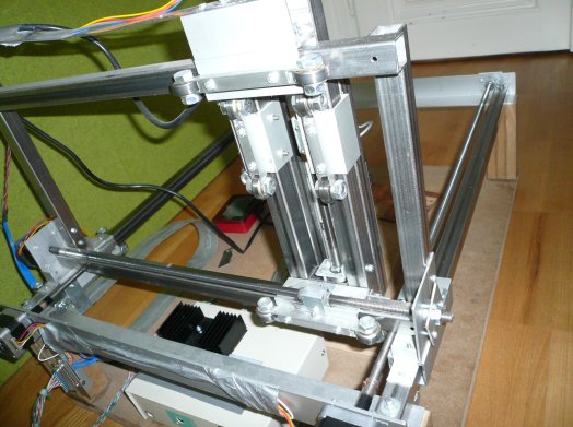
The machine can move at ca. 15 to 20 mm/s, but for milling PCBs, I use only ca. 5 mm/s. You can compute how long it takes to mill a PCB from that. If you like, I can mail you the control software, this software has an emulation mode where you can find out how long a particular sequence of Gcode commands takes.
In practice: Things like the UV dosimeter take half an hour to mill. The electronics for the machine itself takes almost 2 hours per layer and board (two boards, each with two layers). But there's plenty of room for improvements. The PCB to Gcode algorithm is far from perfect.
You can replicate it, of course. I have eagle schematics and PCBs (unfortunately dual layer) for the electronics. There are some parametric drawings for mechanical components, but this part is not yet complete. If you start building such a thing, I can continue the drawings...
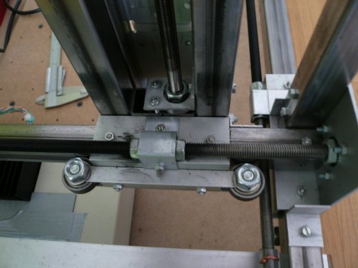
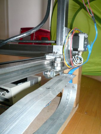
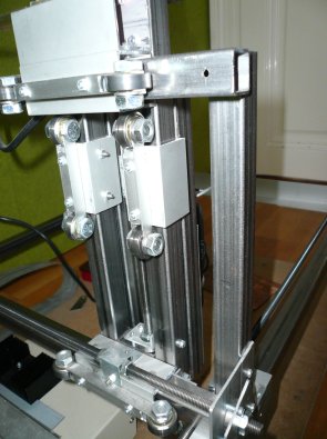
Note, though, that the Z axis needs improvement. It's a bit too elastic now, if there is a force on the mill (not when milling PCBs, but when cutting boards, engraving etc), it may bend by half a millimeter. I have a sketch for a better version, but that has not been built and tested.
Regarding the mills: I have never seen one wear off, all have been damaged before that happens. My spindle motor (a Dremel) is not well balanced and if it goes off-center, the mill breaks. Also if I forget to configure the backlash compensation, the initial acceleration may be so high that the mill breaks when it starts moving. All this happens easily with epoxy boards. The mills should last "forever" on hard paper boards.
Discussion
The total time of milling + soldering vs. building on breadboard/stripboard is probably in the same order of magnitude. The big advantage of milling is that you can do something else while the mill works and that you can be reasonably sure that the circuit matches the schematics. You don't have to debug wiring errors.
The machine is good for prototyping, but not for production, not even for small scale production. The competing technology for production is a photo/etching process. The advantage of the photo/etching process is that it takes the same time, regardless of complexity of the board(s). For production, you can combine several boards to increase complexity so that the photo/etching process wins. For prototyping, you always want to build only one board. And a low complexity board (such as the UV dosimeter) is ready in 40 minutes.
You can use the same mechanics for the RepRap and the PCB milling, and time is not an issue for those who have little money. If you can break down the designs to single sided boards (even with a lot of wire bridges), you cut the milling time in half.
Stripboard is not an option. Somebody who is not experienced with electronics won't be able to do the debugging. And there IS debugging. Count the connections, then multiply by the human error rate (probably around 1%) and you have the number of expected errors.
On throughholes: Is this machine capable of doing throughholes with CNC, or do you do that manually? Do you think it makes sense to do it CNC, or does manual drilling typically suffice?
It's definitely capable of that, of course! And it DOES make sense. Even for etched boards, I would prefer to do the drilling on the CNC. It may be an option to drill all holes in 0.8 mm with the machine and then drill only a couple of them to the desired diameter by hand. This saves the tool change procedure which must be done manually. - S


