D3D Ohio 18.20 Calculations: Difference between revisions
No edit summary |
No edit summary |
||
| Line 30: | Line 30: | ||
During assembly, a slightly (order of a few mm) pipe cut will allow for during cementing the fitting to be "snugged" around the axis it is accommodating. | During assembly, a slightly (order of a few mm) pipe cut will allow for during cementing the fitting to be "snugged" around the axis it is accommodating. | ||
==Belt length== | |||
I first tried the belts cut to 40" | |||
This proved favorable, as it leaves 1.5" slack to make pulling for tension easy. | |||
Revision as of 03:40, 28 May 2018
These are bounds and other calculations for the D3D Ohio printer.
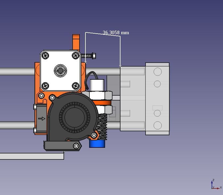
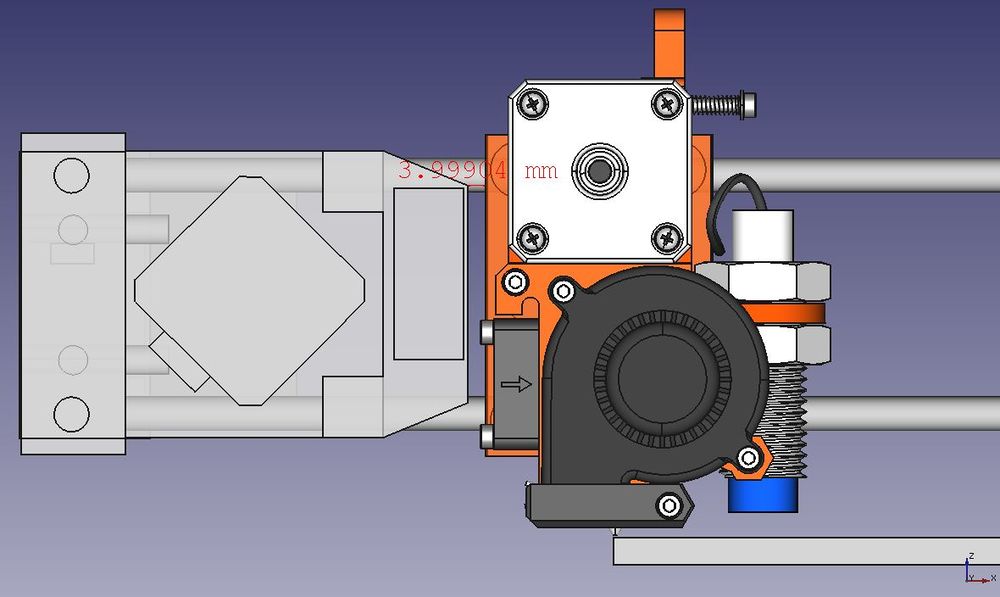
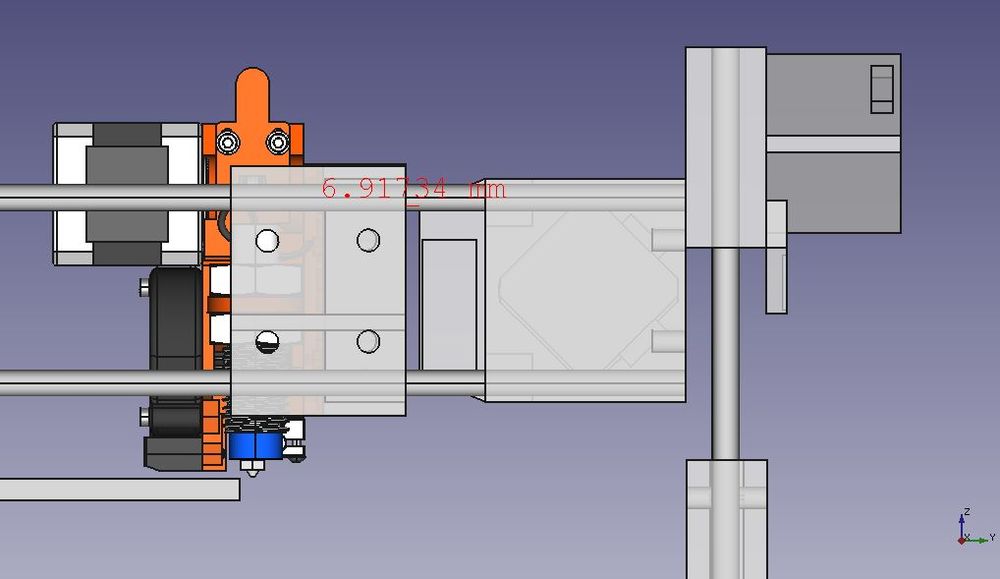
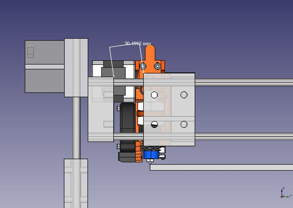
Extruder boundry calculations
Note, the same lengths were used even though the short idler was used. The thinking is this allows plenty of room for dual extruders or other addons.
X plus
X Minus
Y plus
Y minus
PVC frame rendering calculations
the pvc frame is generated by adding the length of an axis plus the diameter of two pipe thicknesses. this initial version uses one inch pipes, so that was added to either end.
The rod length of all axis was 500mm. The outer diameter of a 1" sch 40 pipe is 1.31" so, our length for each axis of the frame was 533.5mm
The PVC pipes generated length was 493.546mm; which could be approximated for a cut length of 493.5mm.
During assembly, a slightly (order of a few mm) pipe cut will allow for during cementing the fitting to be "snugged" around the axis it is accommodating.
Belt length
I first tried the belts cut to 40" This proved favorable, as it leaves 1.5" slack to make pulling for tension easy.


