CEB Press/Manufacturing Instructions/Frame with main cylinder: Difference between revisions
Jump to navigation
Jump to search
William Neal (talk | contribs) No edit summary |
No edit summary |
||
| Line 1: | Line 1: | ||
{{Category=CEB press building instructions}} | {{Category=CEB press building instructions}} | ||
== Tools Required == | ==Tools Required== | ||
*Torch | |||
*Hole Punch | |||
*Mag Drill | |||
*1/2” Allen Wrench | |||
* | ==Materials Required== | ||
* | ===Steel=== | ||
*6” Heavy (7/16”) U-Channel- 274 1/2” | |||
**A- 54” (2); Vertical Members | |||
**B- 20 3/4” (4); Horizontal Members | |||
**C- 28 3/4” (2); Drawer Members | |||
**D- 13” (2); Spacers | |||
*2”x2”x1/4” Angle Iron: | |||
**E1- Cylinder Cross Supports: E1- Horizontals: 20 3/4” (2) | |||
**E2- Cylinder Cross Supports: E2- Verticals: ?? | |||
**F- 6” (2); Dirt Blockers | |||
*1 1/2” DOM Roundstock: 12”; Cylinder Pin: 8 1/2”, Press Foot Filler: 3 1/2” | |||
*1 1/2” Inter Diameter DOM Tubing: 1 1/4” (2); Pin Receptors | |||
*1”x4” Plate: Lower Press Foot: 10” (1) | |||
*1”x6” Plate: Upper Press Foot: 12” (1) | |||
*2” U-Channel: 1.5” (2); Cylinder Spacers | |||
*1” Pipe: 1.5” (2); Cylinder Spacers | |||
*1/4”x1” Flatbar: 13” (1); Magnet holder | |||
*3/8” Rebar: 3.5” (2); Sensor Holder | |||
**For Optional “Jig”: 6”x12” Tubing: 52” | |||
== | ===Nuts and Bolts=== | ||
* | *3/4”x1.5” Bolts (28) | ||
*3/ | *3/4” x 2.5” Bolts (6) | ||
*3/ | *3/4” Steel Nuts (9) | ||
* | *3/4” Galvanized Nuts (40) | ||
* | *3/4” Threaded Rod: 16” | ||
* | |||
===Hydraulics=== | |||
*5”x12” 3000 PSI Hydraulic cylinder [https://www.surpluscenter.com/item.asp?item=9-1143-12&catname=hydraulic Buy] (1) | |||
*3/4” to 3/4” Hydraulic Coupler (2) | |||
*3/4” Female Quick Coupler (1) | |||
*3/4” Male Quick Coupler (1) | |||
==Fabrication Instructions:== | |||
===Step 1: Punch the holes in the horizontal members (A) and in the drawer members (B)=== | |||
[[Image:punchedholes.jpg|thumb|Step 1]] | |||
*In the horizontal members, the holes should be 7/8” in from the long side, and as close as you can get them to the wall of the U-channel. There are 4 holes in each piece. | |||
* In the drawer members, the holes should be 4 7/8” in from the long side, and as close as you can get them to the wall of the U-Channel. There are 4 holes in each piece. | |||
===Step 2: Mag Drill Holes in Verticals.=== | |||
#Gather materials for the “Jig”; this means 6”x12” tubing (52”) and any extra heavy U Channel. If you don't have any laying around, you can use one drawer member, and one spacer on each side. | |||
===To be continued, during the month of August, 2011...=== | |||
[[Image:channel.jpg|thumb|Step 1. Torch or cold-cut channel to size]] | |||
[[Image:Framestanding.jpg|thumb| Step 3]] | |||
== Diagrams == | == Diagrams == | ||
Revision as of 16:43, 22 August 2011
Main > Housing and construction > CEB Press > CEB press building instructions
Tools Required
- Torch
- Hole Punch
- Mag Drill
- 1/2” Allen Wrench
Materials Required
Steel
- 6” Heavy (7/16”) U-Channel- 274 1/2”
- A- 54” (2); Vertical Members
- B- 20 3/4” (4); Horizontal Members
- C- 28 3/4” (2); Drawer Members
- D- 13” (2); Spacers
- 2”x2”x1/4” Angle Iron:
- E1- Cylinder Cross Supports: E1- Horizontals: 20 3/4” (2)
- E2- Cylinder Cross Supports: E2- Verticals: ??
- F- 6” (2); Dirt Blockers
- 1 1/2” DOM Roundstock: 12”; Cylinder Pin: 8 1/2”, Press Foot Filler: 3 1/2”
- 1 1/2” Inter Diameter DOM Tubing: 1 1/4” (2); Pin Receptors
- 1”x4” Plate: Lower Press Foot: 10” (1)
- 1”x6” Plate: Upper Press Foot: 12” (1)
- 2” U-Channel: 1.5” (2); Cylinder Spacers
- 1” Pipe: 1.5” (2); Cylinder Spacers
- 1/4”x1” Flatbar: 13” (1); Magnet holder
- 3/8” Rebar: 3.5” (2); Sensor Holder
- For Optional “Jig”: 6”x12” Tubing: 52”
Nuts and Bolts
- 3/4”x1.5” Bolts (28)
- 3/4” x 2.5” Bolts (6)
- 3/4” Steel Nuts (9)
- 3/4” Galvanized Nuts (40)
- 3/4” Threaded Rod: 16”
Hydraulics
- 5”x12” 3000 PSI Hydraulic cylinder Buy (1)
- 3/4” to 3/4” Hydraulic Coupler (2)
- 3/4” Female Quick Coupler (1)
- 3/4” Male Quick Coupler (1)
Fabrication Instructions:
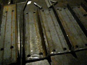
Step 1: Punch the holes in the horizontal members (A) and in the drawer members (B)
- In the horizontal members, the holes should be 7/8” in from the long side, and as close as you can get them to the wall of the U-channel. There are 4 holes in each piece.
- In the drawer members, the holes should be 4 7/8” in from the long side, and as close as you can get them to the wall of the U-Channel. There are 4 holes in each piece.
Step 2: Mag Drill Holes in Verticals.
- Gather materials for the “Jig”; this means 6”x12” tubing (52”) and any extra heavy U Channel. If you don't have any laying around, you can use one drawer member, and one spacer on each side.
To be continued, during the month of August, 2011...
Diagrams
Step 1: Gather the Form Pieces
Step 2: Put the Form Pieces Together
Step 3: Line the Vertical Beams along the Form and C-Clamp them in Place
Step 4: Place One Each of the Upper and Lower Cross Beams
Step 5: Flip the Frame
Step 6: Place the Remaining Cross Beams
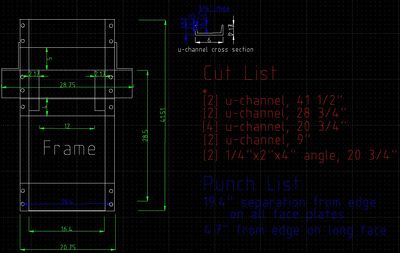
This diagram shows the pieces needed for the frame. Click to enlarge:

Video Explantion


