CEB 3D Printer: Difference between revisions
mNo edit summary |
mNo edit summary |
||
| Line 154: | Line 154: | ||
<u>'''Read Encoders Function:'''</u> Read digital encoders. This function will need to be written after testing is done, but I can provide skeleton code soon. | |||
| Line 243: | Line 244: | ||
<u>'''Write to Motors Function:'''</u> Digital write to speed controllers (output is amplified using the higher current & voltage power source from 12V batteries. This function, just like the encoders will need to be written after/while testing is done, but I can provide skeleton code soon. | |||
<u>'''IRC Online Meeting Schedule:'''</u> This is temporary section I'm experimenting with which doesn't quite belong here. | |||
<div style="text-align: center;"> | <div style="text-align: center;"> | ||
Revision as of 08:12, 20 December 2011
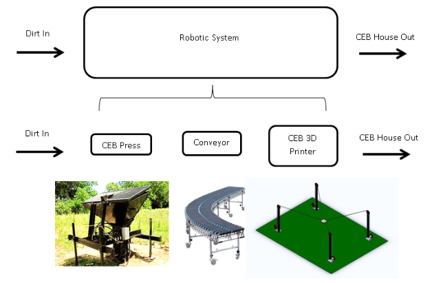
Concept (Illustrated Below): This idea is to develop an automated brick-laying system that can build homes from the ground up, literally. Using a combination of the CEB Press, a conveyor belt, gripper, and a common machine configuration (TBD), the machine acts like a large 3D printer which picks and places compressed bricks robotically.
Two video animations, originally made as Java applets, illustrate two such designs:
Animation (Gantry Design)
Animation (Cable Design)
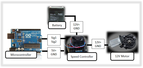
High-Level Actuator Architecture:
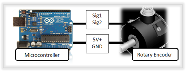
High-Level Feedback Architecture:
Sample Source Code:
|
Pseudo Code
|
Arduino Code |
| DECLARE VARIABLES & FUNCTIONS Initialize Output Channels // Tell microcontroller which pins are output Initialize Input Channels // Tell microcontroller which pins are input MAIN LOOP For Motors 1 to 4: Read Encoder Values Calculate Motor Output to Achieve Desired Position Write to Motor Output Channel // Note: the motor signal is sent to a speed controller // to be amplified END FOR LOOP END MAIN LOOP |
void setup() { pinMode(2, OUTPUT); // to Base motor 1 pinMode(3, OUTPUT); // to Base motor 2 pinMode(4, OUTPUT); // to Base motor 3 pinMode(5, OUTPUT); // to Base motor 4 pinMode(6, INPUT); // from digital Encoder 1 pinMode(7, INPUT); // from digital Encoder 2 pinMode(8, INPUT); // from digital Encoder 3 pinMode(9, INPUT); // from digital Encoder 4 } void loop() { for (int motorIndex = 0; motorIndex < 3; motorIndex++) { read_encoders(); pid(); write_to_motors(); } } |
Read Encoders Function: Read digital encoders. This function will need to be written after testing is done, but I can provide skeleton code soon.
Calculate Length Function: Now that desire gripper position & all 4 current lengths are known, desired length for each cable can be calculated.
float px, py, pz; // p (x,y,z) is the current position of the gripper
float dpx, dpy, dpz; // p (x,y,z) is the desired position of the gripper

float Bheight = 12.0, Blength = 18.0, Bwidth = 12.0; // Base dimensions at 12'x18'x12'

float B1x = 0.0,     B1y = 0.0,       B1z = Bheight; // top point of base rod 1
float B2x = 0.0,     B2y = Blength,   B2z = Bheight; // top point of base rod 2
float B3x = Bwidth,  B3y = Blength,   B3z = Bheight; // top point of base rod 3
float B4x = Bwidth,  B4y = Blength,   B4z = Bheight; // top point of base rod 4

float L1,L2,L3,L4, dL1,dL2,dL3,dL4; // Current and desired length variables

// This function calculates the length that each of the cables
// must be in order to attain the desired gripper position.
void get_lengths()
{

  // Lengths are determined from top of base rod to gripper,
  // so this does not include length from motor to pulley
  // at the top of the rod.

  L1 = dist3d(B1x, B1y, B1z, px,py,pz);  // Length of cable 1 in feet
  L2 = dist3d(B2x, B2y, B2z, px,py,pz);  // Length of cable 2 in feet
  L3 = dist3d(B3x, B3y, B3z, px,py,pz);  // Length of cable 3 in feet
  L4 = dist3d(B4x, B4y, B4z, px,py,pz);  // Length of cable 4 in feet

  // Desired lengths calculated the same way.

  dL1 = dist3d(B1x, B1y, B1z, dpx,dpy,dpz); // Desired length of cable 1
  dL2 = dist3d(B2x, B2y, B2z, dpx,dpy,dpz); // Desired length of cable 2
  dL3 = dist3d(B3x, B3y, B3z, dpx,dpy,dpz); // Desired length of cable 3
  dL4 = dist3d(B4x, B4y, B4z, dpx,dpy,dpz); // Desired length of cable 4

}

//____________CALCULATE_THE_3-D_DISTANCE_(L-3_NORM)________________//
float dist3d(float p1x, float p1y, float p1z, float p2x, float p2y, float p2z)
{
  float dist3 = sqrt((p2x-p1x)*(p2x-p1x) + (p2y-p1y)*(p2y-p1y) + (p2z-p1z)*(p2z-p1z));
  return dist3;
}
PID Function: Now that desired length and current length are known, motor output and direction for each motor can be calculated.
float[] err = new float[4];  // error array
float[] dir = new float[4];  // direction array
float[] out = new float[4];  // output array

float kp = 500;  // this gain is arbitrary, but must be positive
float Prop;      // Variable used for proportional gain.
float max_output = 100; // Saturate the output at 100, also arbitrary

//___________________PID_FUNCTION______________________//
void pid() // Actually just P for simplicity's sake
{

  Prop = kp*err[motorIndex]; // P = const*(desired_length - current_length)
  out[motorIndex] = Prop;    // output = P;

  if (out[motorIndex] > 0)  dir[motorIndex] = 1; // Get direction either 1
  else dir[motorIndex] = 0;                      // or 0

  constrain(out[motorIndex], -max_output, max_output); // saturate output
  out[motorIndex] = abs(out[motorIndex]); // now that we know direction, we
                                          // just need the absolute output
}
Write to Motors Function: Digital write to speed controllers (output is amplified using the higher current & voltage power source from 12V batteries. This function, just like the encoders will need to be written after/while testing is done, but I can provide skeleton code soon.
IRC Online Meeting Schedule: This is temporary section I'm experimenting with which doesn't quite belong here.
IRC Experimental Meeting Test Chart: This chart is used to display group meeting times on the OSE Internet Relay Chat (IRC) http://opensourceecology.org/wiki/Irc where groups can discuss project ideas and progress with realtime feedback. Group member names, IRC chat usernames, and status of sub-projects are listed.
| Task | Name/Pseudonym | IRC Username | Status of Project | Extra |
|---|---|---|---|---|
| Motor Testing | vc_nepo | vc_nepo | 10 % | Link |
| Encoder | User B | userBonIRC | 20 % | |
| Material Spec | User C | userConIRC | Complete |


