Larry Dobson- Gassifer/Boiler: Difference between revisions
Alex Briggs (talk | contribs) |
Alex Briggs (talk | contribs) No edit summary |
||
| Line 83: | Line 83: | ||
==='''Gasification Overview:'''=== | ==='''Gasification Overview:'''=== | ||
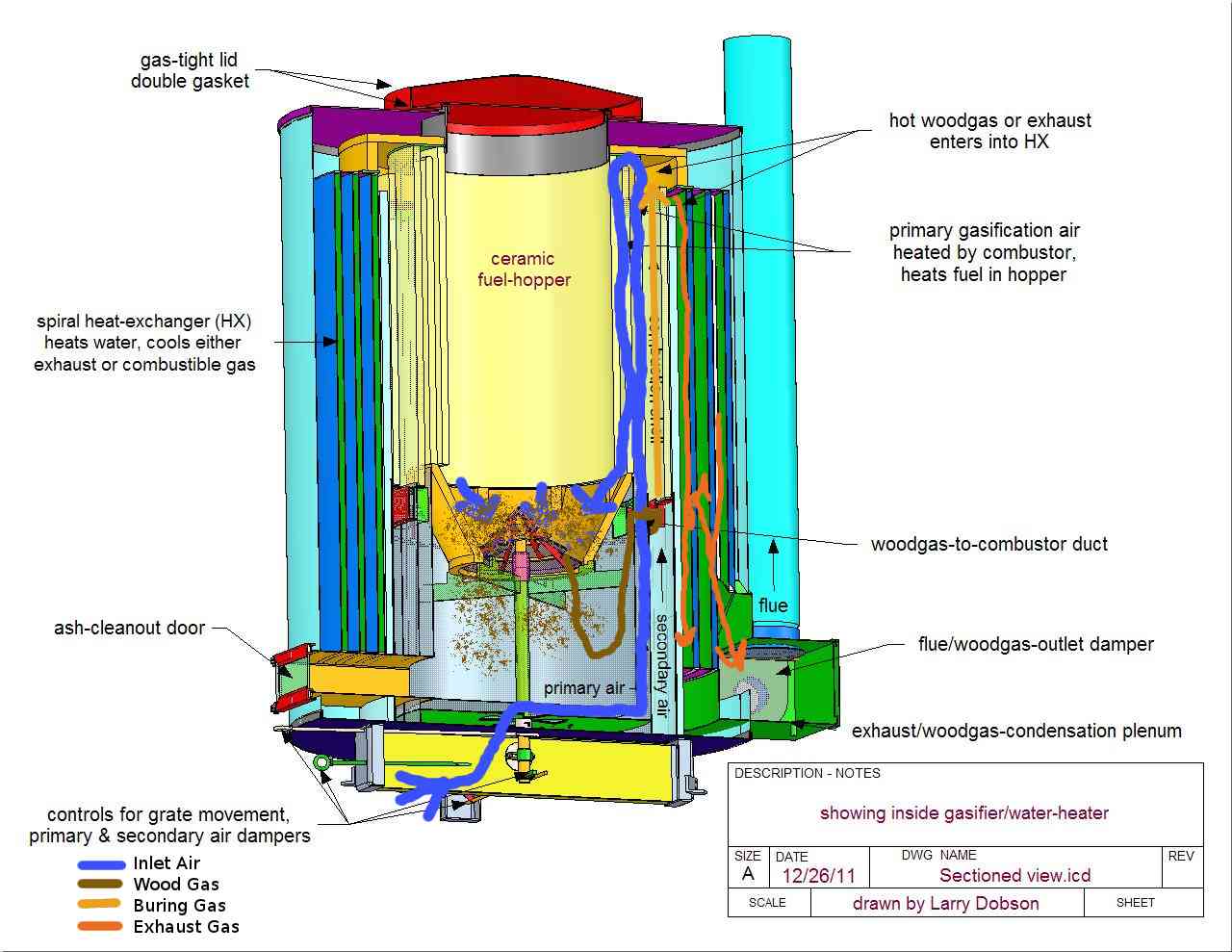
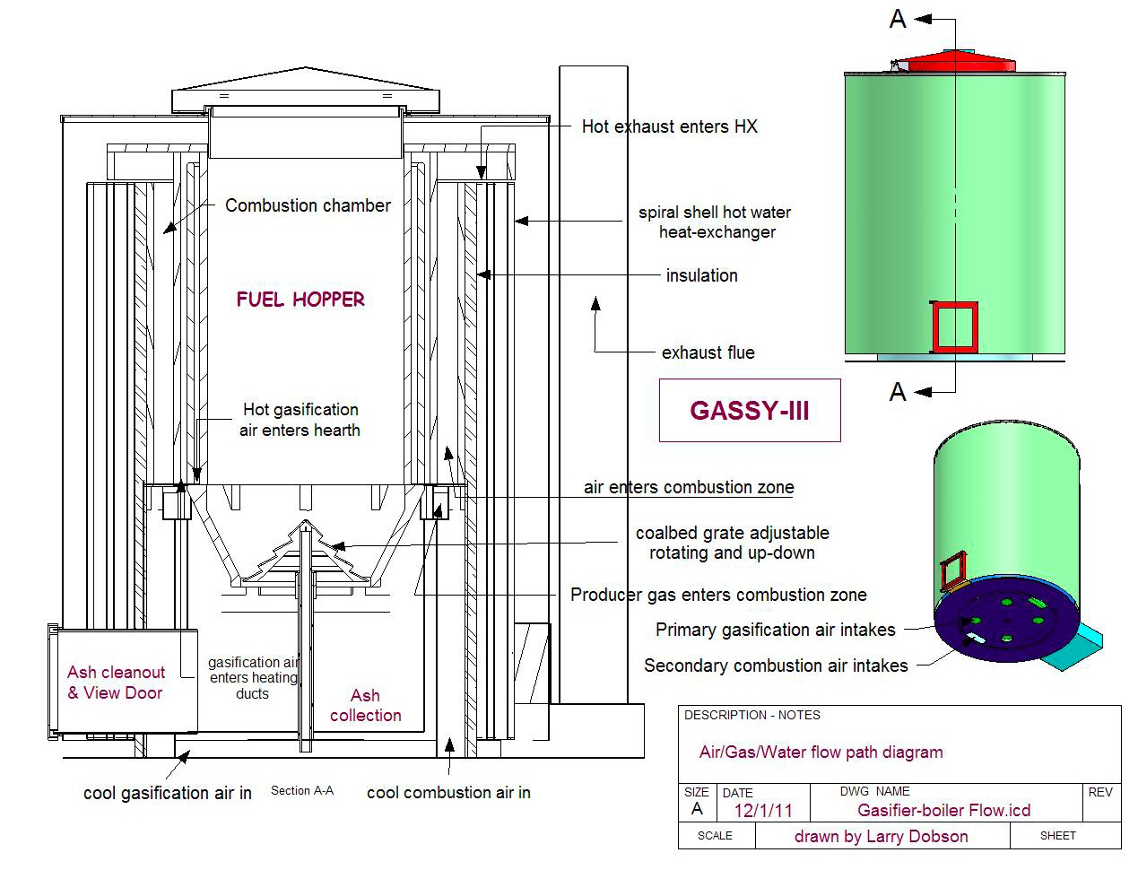
See below diagram to orient description | |||
*Primary air for gasification enters through holes in the periphery of the bottom plate & travels to the rotating air damper in the center of the plate above. This removes heat from the bottom plate and bottom of ash-shell, preheating the air. The air then travels up outside the ash-shell, extracting more heat, then enters the ceramic duct next to the combustion shell, where it is heated by the burning gas (or 1400F hot producer-gas), rises up over the ceramic shell to the inside, then travels down next to the cooler hopper shell, heating the fuel inside as it flows. | |||
*The hot primary air exits at the base of the hopper, where it volatizes the fuel and moisture and burns it until the oxygen-starved gas travels down through the coal bed. The chemical reactions at this point are all endothermic, taking heat away from the hot gas and charcoal as more combustible CO and H2 are liberated. There are many variables for different fuels, so we may need to develop several modular grate designs to provide an even gasification rate through a uniform coal bed of the depth to optimize woodgas production or biochar. The fuel gas can be generated cooler and wetter and sootier for direct combustion --- it all burns clean at the right temperature and residence time, with the right amount of air mixed evenly. Within the turn-down range of super-clean combustion, there will be a narrower optimum range for production of a clean gas for I.C. engines, phase-change refrigerators, and other such remote applications. | |||
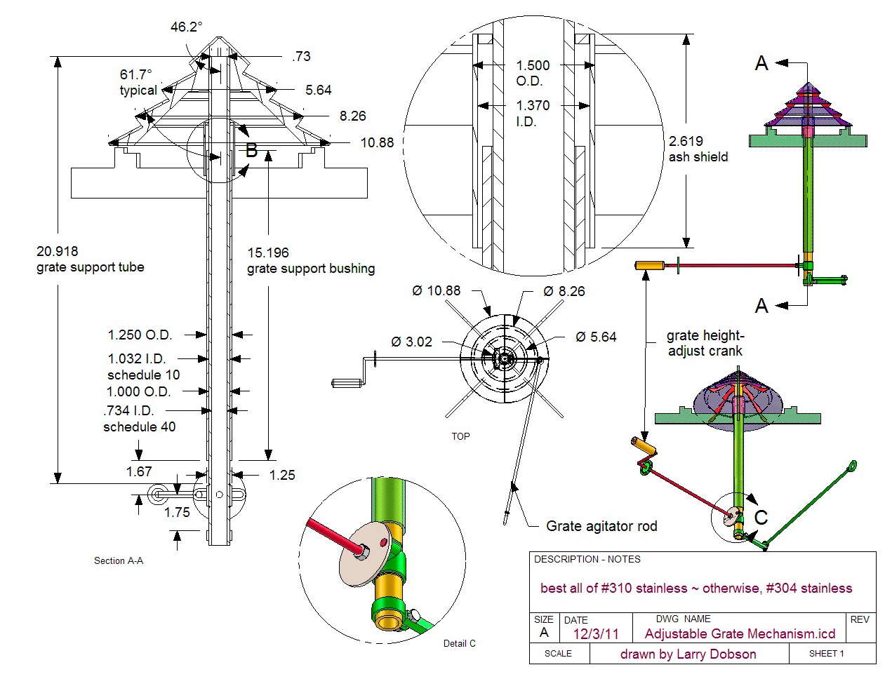
*The cooler, but still hot, woodgas (producer gas, biomass gas, garbage gas) exits from the hearth through the central conical grate, between conical slats that provide large openings that prevent the fuel from falling through because they provide overhanging ledges. This design has proven quite superior to just holes, which let through small aggregate fuel particles and easily get clogged with charcoal and ash. The grate is adjustable up and down to optimize the charcoal depth, and can be agitated by turning to drop out ash (and biochar if that is also wanted). Ash collects below, where it can be removed through the front access door. | |||
*The hot fuel gas then flows through the four woodgas-to-combustor-ducts at the top of the ash bin. Most of the ash is deposited here, since the gas must turn 180 degrees to flow upward, while the ash falls with gravity. | |||
* In the annular combustor ring, when in combustion mode, the hot gas is mixed with secondary air, where it burns cleanly due to hot temperature and even mixing of gas and air. The secondary combustion air enters two dampers in the bottom plate, where it is heated by the primary air shell, also cooling the lower region and saving on insulation. | |||
*The combustor preheats the primary gasification air, which creates a higher quality gas while lowering the temperature of combustion, which reduces deterioration of materials and lowers levels of NOx pollutants. The outer shell of the combustor is insulated from the heat exchanger (HX) to facilitate optimum combustion and maximum HX efficiency. | |||
*If the system is being operated as a gasifier, no combustion air is introduced and the hot producer gas performs the same heat-transfer function, although not as intense as when combustion is present. | |||
From here the hot gas enters the Heat Exchanger. In these diagrams the heat exchanger is optimized for hot water production, and so this part of the design will change to be better suited to output superheated steam for steam power generation. This article will be updated as soon as it is completed. | |||
[[File:Air-gas flow.JPG]] | [[File:Air-gas flow.JPG]] | ||
Revision as of 15:57, 2 August 2012
Building & Testing a Gasifier/Steam Generator
by Larry Dobson 7/31/12
www.fundamentalform.com , lad@fundamentalform.com
Abstract:
Civilization’s almost total dependence on diminishing fossil-fuel resources is destroying our planet and must be changed quickly. The gasifier-boiler that this proposal aims to build, based on 38 years of R&D, will be capable of both: producing high quality steam at 650 degrees and 800 psi for steam power production, and generating higher quality syngas than any other model on the market. This internal double-functionality is unique to this machine, and would be achieved as easily as turning a damper. This residential-size gasifier/boiler will convert locally available waste biomass material from forestry, agricultural, processing industries and municipal waste streams, much of which is now a costly disposal problem, into valuable decentralized energy utilizing existing I.C. and prototyped steam engines. This integrated system can convert a greater variety of feedstock, size and moisture content at higher efficiencies than currently existing technologies. Such efficient decentralized energy production has the potential to greatly assist local energy self reliance, create local employment, keep energy dollars in the community and convert costly landfill waste disposal into valuable energy generation.
According to a new study, forest biomass could replace as much as 28% of the liquid fossil fuel now being used for industrial and commercial heating in the Northeastern US. In the Pacific Northwest alone, about one quad (1,000 trillion BTUs) of biomass residues are physically generated each year. This is equivalent to 160 million barrels of oil, or $10 billion per year in residential fuel oil. It represents the heat equivalent of 1½ times the annual electric power consumption of the Pacific Northwest. This scenario is repeated across the nation and around the world.
Detailed plans have already been drawn up and are now offered free open-source on the OSE website as part of the GVCS (http://opensourceecology.org/wiki/Gasifier_Burner_with_Heat_Exchanger_Prototype_I ). This will not only make the technology available to all, it will facilitate further R&D work to perfect the design, fabrication, operation and longevity of the technology.
This first prototype will be fabricated by Larry Dobson in Washington State, tested, then sent to the Factor-E-Farm to heat, provide steam power and producer gas for a variety of applications, from kilns & forges to I.C. engines. Should the proposal be accepted, the Production will take place over the months of August-October, testing from October-November, and the finished product can be expected at Factor e Farm in December.
Economics Analysis
This project is of high economic and symbolic significance to Open Source Ecology. Symbolically it will be a major milestone- once incorporated into an energy system with the steam engine- of reaching fossil fuel independence by sourcing local biomass as an energy source. The biochar byproduct from this process will serve to enhance the fertility of the Factor e Farm (FeF), in contrast to the poisoning effect that the use of fossil fuels have on our world. Maybe even more significant will be the economic effect, as FeF will soon be able to produce its own biomass and energy from free solar inputs, leaving only labor costs (which are typically low at FeF, and can be reduced with the completion of a microcombine).
Even more significant could be the retail prospects for this project. Following the model being adopted for the CEB, the energy system could be produced on site and sold around the country to fund further FeF projects. While the CEB has a considerable market, it is a more specialized use, compared with the demand for (particularly green) energy. Production costs can reasonably be considered to be low since the gasifier requires no complex external components, and much of the budget in this proposal is dedicated to testing equipment which is a one-time cost.
The extensions could drive this cost down dramatically, since gasifier could heat a kiln which could even potentially use local FeF clay for the creation of the refractory. Even a syngas foundry could potentially be developed, and at this point FeF would retain all the value added from scrap metal and virgin clay into a fully functioning Gasifier/Steam Engine energy system- which in turn will be capable of providing customers with extensive energy savings. Following the model of many solar companies FeF could provide complete energy services to customers (including potentially growing and delivering biomass and recouping biochar) while collecting the margin of savings that results from the customer's switch from grid to biomass energy- this could make the transition extremely accessible to customers of all economic backgrounds, and ensure and essentially unlimited market.
Deliverables
As detailed on the above webpage, I have completed detailed plans for a heating system with the following features:
A residential-size hot water heater, named “Roundy”, fueled with wood, agricultural waste, pellets, wood chips, corn cobs and other biomass fuels, able to operate on natural convection flow or fan. This unit will also operate as a stand-alone gasifier, generating woodgas of a quality for running an I.C. engine or other gas-fueled appliances, such as refrigerator, cookstove, foundry kiln, etc., or being modified to produce superheated steam instead. Size will heat an insulated building of about 3000sq.ft.
Configuration will include gasifier fuel hopper with combustion chamber and heat-exchanger modules integrated into one unit. Gasifier will include manual grate adjustment and rotation for ash-separation at coal-bed, ash-collection with manual removal, and manual air-intake dampers for gasifier and combustor. Steam at 650 degrees and 800 psi will be produced inside a concentric tube-and-annulus heat exchanger (HX) that will be of spiral design of sufficient efficiency to allow condensation of moisture from flue gases on low settings and high efficiency. The plans include 62 pages of detailed drawings, 15 pix, 11 pages of explanation and instruction, 43 pages of CNC cutout drawings.
From these plans, I will build and test this prototype over a 3-month period, beginning from signing of the construction grant contract. Deliverables include:
- The complete gasifier/furnace, including:
- Variable-speed high-pressure fan to test the full range of operating parameters
- Water pump
- stainless stovepipe ~ including bypass + unions & elbows
- 304 Stainless steel parts, laser-cut and welded
- castable ceramic refractory
- insulation blanket
- imbedded Type-K thermocouples to monitor
- 1 = gasification flame temp
- 2 = gas combustion temp
- 3 = preheated gasification air temp
- 4 = exhaust or exiting gas temp
- 5 = hottest gas temp
- 6 = top of hopper temp
- 7 = water jacket cold inlet
- 8 = water jacket hot exit
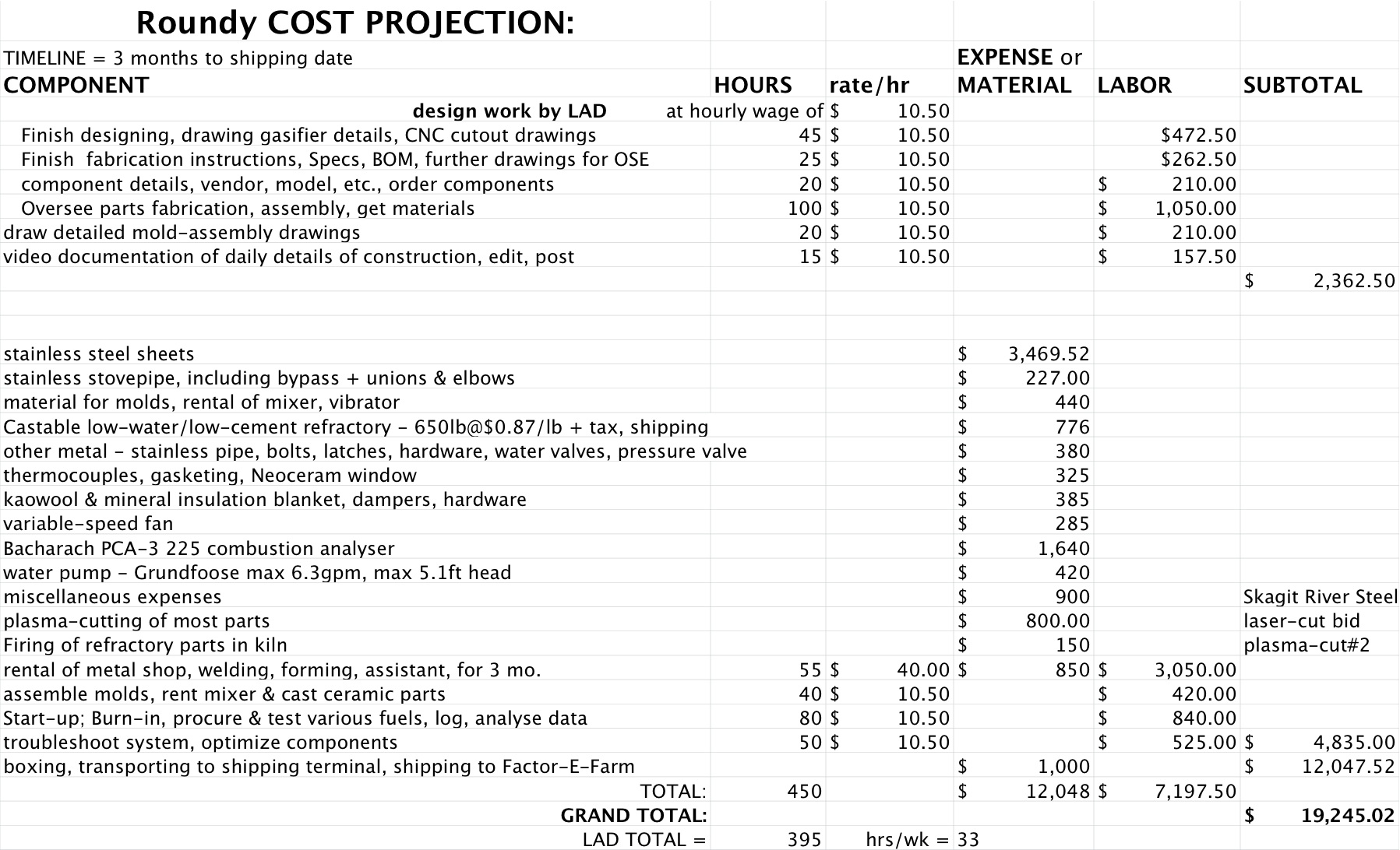
- A Bacharach combustion analyzer to monitor O2, CO, flue temperature, stack temperature, combustion air temperature, draft and differential pressure $1640
- preparing, transporting to shipping terminal, shipping to Factor-E-Farm - $1000
2012 Pricing for Competitive Hydronic Furnaces
| Furnace | Cost | Weight (lb) | Features | Unit Size(ft^3) | Firebox Size (ft^3) |
| Roundy | 1400 | This is both hydronic furnace and straight gasifier in one. Handles much greater variety of fuel size & moisture content. Has much larger HX surface area (140ft2) for high-efficiency & clean exhaust/producer-gas in condensing mode. Very high & efficient turn-down for optimumized heat/gas production. Exhaust temp 130 - 300F, far lower than all competition. Stainless steel and refractory ceramic for longevity - most oth | 61 | 4.7 | |
| GEK® TOTTI™ 20kW Ready to Assemble | $ 5,585 | ? | with exhaust preheat & fuel drying. 20kW is 68,000Btu/hr = half or less of Roundy | ? | ? |
| Victory Gasifier (2012 price) | $15,134 | 450 | 5-15kW,incl.H20 HX,fuel pre-drying bin,cooler,filter,blower, stainless construction, no furnace | ? | 4.7 |
| Portage & Main outdoor water furnace Economizer IDM 100 | $ 8,500 | 1600 | firetube water boiler | 45 | 7 |
| Optimizer 250 | $ 11,500 | 3030 | up to 250K Btu/hr, designed for batch burn & hot water storage | 145 | 11 |
| Garn 1500 | $ 16,000 | 3200 | |||
| Tarm-30 | $ 8,000 | 1080 | 600F flue temperature on high burn | ? | 4 |
| Greenwood Frontier CX | ? | 1480 | 750lb refractory | 50.7 | 8.4 |
| New Horizon BioMass 40 | $ 6,600 | 1212 | |||
| AAA Outdoor Boiler wood/coal gasification boiler - R120 | $ 6,000 | 1,652 | flue temp = 310-340F, claimed 91% (impossible with such high exhaust Temp. | 42.8 | 5.4 |
This gasifier is unique in several ways and I have found nothing on the market similar, so this list is for rough comparison. Since it is both an efficient gasifier/gas filter-cooler and a condensing steam boiler of greater efficiency and cleanliness than probably any of the above, its true value is greater than the sum of its parts, which could easily compete with the above at $25,000 if commercialized. Prototype designing, building and testing usually takes several times the funding as the finished product will cost, simply because of the inefficiencies of one-off fabricating for the first time, mold & jig-making, revising parts & drawings, spec’ing out, ordering and delivering all the components, subcontracting & coordinating, rental of equipment, unanticipated complications, etc.
This project also includes instrumentation and testing of the prototype with different fuels with variations in moisture content, constituents, size profiles, and ash-content, such as logs, branches, chips, bark, pellets, agricultural residue, residential waste, manure, and MSW. Testing will include temperature and emission profiles for these fuels at various heat through puts for operation in steam generator mode and gasifier mode, adjusting and rotating the movable grate, variable-speed fan and other equipment variables.
Fabrication of the unit is expected to be finished within 2 months, with testing and optimization to take up the remaining month. This design has the potential for scaling both up and down, with the smallest size suitable for a small cabin or mobile home. Many variations in design for different applications and fuels will be suggested, from a fully-automated home energy system to a basic gasifier for mobile transportation application.
Gasification Overview:
See below diagram to orient description
- Primary air for gasification enters through holes in the periphery of the bottom plate & travels to the rotating air damper in the center of the plate above. This removes heat from the bottom plate and bottom of ash-shell, preheating the air. The air then travels up outside the ash-shell, extracting more heat, then enters the ceramic duct next to the combustion shell, where it is heated by the burning gas (or 1400F hot producer-gas), rises up over the ceramic shell to the inside, then travels down next to the cooler hopper shell, heating the fuel inside as it flows.
- The hot primary air exits at the base of the hopper, where it volatizes the fuel and moisture and burns it until the oxygen-starved gas travels down through the coal bed. The chemical reactions at this point are all endothermic, taking heat away from the hot gas and charcoal as more combustible CO and H2 are liberated. There are many variables for different fuels, so we may need to develop several modular grate designs to provide an even gasification rate through a uniform coal bed of the depth to optimize woodgas production or biochar. The fuel gas can be generated cooler and wetter and sootier for direct combustion --- it all burns clean at the right temperature and residence time, with the right amount of air mixed evenly. Within the turn-down range of super-clean combustion, there will be a narrower optimum range for production of a clean gas for I.C. engines, phase-change refrigerators, and other such remote applications.
- The cooler, but still hot, woodgas (producer gas, biomass gas, garbage gas) exits from the hearth through the central conical grate, between conical slats that provide large openings that prevent the fuel from falling through because they provide overhanging ledges. This design has proven quite superior to just holes, which let through small aggregate fuel particles and easily get clogged with charcoal and ash. The grate is adjustable up and down to optimize the charcoal depth, and can be agitated by turning to drop out ash (and biochar if that is also wanted). Ash collects below, where it can be removed through the front access door.
- The hot fuel gas then flows through the four woodgas-to-combustor-ducts at the top of the ash bin. Most of the ash is deposited here, since the gas must turn 180 degrees to flow upward, while the ash falls with gravity.
- In the annular combustor ring, when in combustion mode, the hot gas is mixed with secondary air, where it burns cleanly due to hot temperature and even mixing of gas and air. The secondary combustion air enters two dampers in the bottom plate, where it is heated by the primary air shell, also cooling the lower region and saving on insulation.
- The combustor preheats the primary gasification air, which creates a higher quality gas while lowering the temperature of combustion, which reduces deterioration of materials and lowers levels of NOx pollutants. The outer shell of the combustor is insulated from the heat exchanger (HX) to facilitate optimum combustion and maximum HX efficiency.
- If the system is being operated as a gasifier, no combustion air is introduced and the hot producer gas performs the same heat-transfer function, although not as intense as when combustion is present.
From here the hot gas enters the Heat Exchanger. In these diagrams the heat exchanger is optimized for hot water production, and so this part of the design will change to be better suited to output superheated steam for steam power generation. This article will be updated as soon as it is completed.
Heat Exchanger
Whether the gasifier is run to produce steam or woodgas, the hot exhausts flow out of the combustion chamber and through a heat exchanger where their energy, in the form of heat, is caught. The design shown in the above pictures is ideal for hot water generation, because the parallel plates give a huge amount of surface area for heat exchange to occur, and because the vertical orientation of the walls allows the fly ash to fall out of the exhaust gasses under the passive force of gravity. This means that as the exhaust cools the ash settles, and by the exit the woodgas is designed to be clean enough to use directly in an I.C. engine or other application, without filtration.
This design has many advantages, however for steam production it will not work. The pressure generated by the steam cannot be practically contained within these spiral-wrapped parallel plates, and instead must use a strong coil of steel. This then presents the challenges that the parallel plates solved, that of increasing the surface area for heat exchange and fly ash precipitation, as well as the geometry of fly ash removal from the system.
This portion of the design is still being worked with, however it will consist of an outer annulus (shell) which contains the exhaust gas, with a steam coil inside of it. One option is to wrap the steam coil in a helix around the combustion shell, which use a simple geometry and maximize the conductive heat gain from the combustion shell. A problem with this design would be the build-up of fly ash, particularly in the hot top regions, which would reduce heat exchange and could possibly block up the system. Another possibility is to weld the steam bars vertically in a cage surrounding the combustion shell, which would have less problems with fly ash build-up, but would be much harder to manufacture, and has safety concerns with all the welds holding high pressure steam.
As soon as a final design is decided upon it will be modeled, and, once done, this document will be updated.
Start-up Procedure:
The gasifier is started similar to a normal woodstove, with crumpled paper and dry kindling loaded into the hopper first, lit with the induction fan on low, then the main fuel is loaded on top of this. Alternatively, with fuel already in the hopper, crumpled paper is stuffed into the ash-door and lit, the induction fan is started, then propane gas is introduced through the central grate pipe until the fuel is burning well.
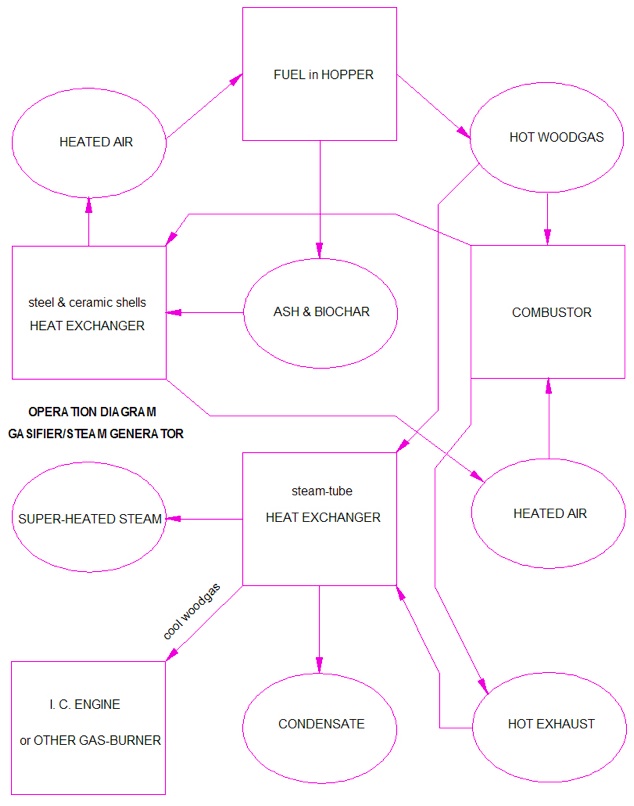
Systems Engineering Breakdown Diagram
OSE Specifications Assessment
This energy system is designed in three modules that can be replaced or utilized with other modules for other functions, the gasifier hopper and air preheat assembly; the ash-collection, air distribution and control section; and the heat-exchanger section. Because biomass and waste gasification is such a complex process with so many variables, this prototype is designed to demonstrate the highest potential in variety of usable fuels; high efficiency from intense air-preheating and strict utilization of thermodynamic design principles; and integration of components in a feedback system that is far more than the sum of its parts. It is designed as a platform of excellence from which to develop a whole new set of spin-off energy technologies, such as simpler fuel-specific gasifiers & heaters, a steam-engine or Stirling-engine or thermovoltaic-cell power-source, low-tech, low-cost gasifiers and ovens made from local materials, light-weight mobile gasifiers for I.C. vehicle fuel, and as a heat-source for kilns, forges, glass-furnaces, foundries, thermo-refrigeration systems, etc.. Future improvements will incorporate electronic control design and circuitry being developed as another GVCS project.
A major advantage of this energy system is it's unique versatility, being able to produce either high quality steam, or low temperature heat as well as woodgas fuel. Another is the ubiquitous free fuel source, which replaces fossil-fuel with decentralized local waste materials, thereby creating local energy, local investment, local jobs, local control.
Resources
This project will be pursued at the inventor’s location on Whidbey Island, WA, utilizing a local CNC-plasma cutter and metal fabrication shop. Metal, ceramic and other components will be ordered from the closest available sources, considering quality and price. When testing is finished, it will then be shipped to Factor E Farm, where I will visit for installation and startup.
Timeline:
(note, documentation is not listed in this timeline, but will take place throughout every part of it)
July 29th- Proposal Submission
August 10th- Proposal Approval
- redesign: adaptation for low cost steam production- (change sheetmetal thickness throughout the components, redoing most of the 2D spec drawings, changing the configuration of the HX to Steam, change the slope of the air-transfer ducts, lay out the most efficient cutout pattern for the plasma cutter)
- Assitant's (alex briggs) arrival in Washington state
- 3 weeks
August 31st- order needed components, finish detailed fabrication procedure
- 1 week
Sept 7th- arrival of castable ceramic -make ceramic molds, rent mixer & vibrator, cast ceramic parts
- 1 week
September 14th -Plasma cut needed components, send ceramic parts to Kiln
- 1 weeks
September 21st brake/fit/weld components in assembly metal shop
- 2 weeks
Sept 29th- send ceramic parts to Kiln -finish brake/fit/welding, assemble, check + begin testing
- 3 weeks
October 20th
Testing- 1 month, then shipped to Factor e
Possible Delay allotment- 3 weeks-
Shipment Date: no later than December 10th Gassifier should arrive in MO, fully documented and tested, in early December (dependent on shipping time)
Budget
Over the past 3 years, especially this last year, the price of manufacturing raw materials, especially stainless steel, has risen sharply. This has driven the cost of this project up substantially. This price increase is reflected in the increased cost of factory-manufactured furnaces and gasifiers as well. Because the steel in this appliance must withstand both red-hot temperatures and condensing water-vapor, stainless steel is necessary for most components. I have chosen #304 stainless because it is the cheapest Nickel/chromium stainless on the market. When we know where we can use thinner stainless steel and substitute cheaper materials, and how to build components in jig-time, for the next ones overall costs will come down.
My normal consulting, designing and building fee has been $40 to $100/hr on past projects. While I had originally proposed a $40 labor fee, since this seems to be a low-budget, not-for-profit, out-to-improve-the-world organization, I have lowered my rate to $10.50/hr, which I really need to meet my expenses. If more labor is necessary than projected, then I will be putting in more hours for the same income. Been there, done that. The plasma-cutting shop and metal shop where the prototype will be built charge a very low fee for their services, compared with other facilities I have used in the past. This represents a significant savings on the project. Although I have sourced most of the hardware components from specific companies, I have found cheaper sources and will continue to look for lower-cost or higher-quality products and sources as I order components.
Three bids on the metal plus cutting range from $4,470 (metal from Alaskan Copper, plasma-cut) to $9,534 (laser-cut from Automated Metal Technologies)
Assessment
Success stages of the project will be:
- Wrapping, clamping and welding the heat-exchanger module so it is water-&-gas-tight, in a systematic approach that I can document on video.
- Assembling and welding all the inner components so their alignment is true and they are gas-tight
- Creating dense, flawless castings that fit accurately together and in alignment with all other parts
- Finish successfully all the assembly of components, including grate up-down-&-agitation mechanism, smooth tight damper actuation, gas-tight lid and doors
- Video documenting of the stages of construction, operation & testing
- Successful operation of thermocouples, pressure sensors, variable-speed fan, combustion analyser, computer-interface
- Production of clean exhaust and condensate throughout an extensive range of operation, clean producer-gas generation within a broad range of throughputs, fuel moisture content and fuel sizing
- Extensive and clear analysis of operating parameters of gasifier and furnace relative to various temperature parameters, excess air, fuel type and moisture content, turn-down ratio and limits of operation for cleanliness, efficiency and longevity
Failure Mode Analysis and Recovery Plan
Week by week assessments of goals, blocks and accomplishments will be conducted and published online, however at present, with Larry Dobson's extensive experience in the field and the employment of the precision CNC plasma cutter and professional metal shop, failure seems unlikely and unpredictable. Should problems arise they will be addressed quickly and openly with respect to Open Source Ecology.
