Solenoid Driver: Difference between revisions
Jump to navigation
Jump to search
No edit summary |
|||
| Line 1: | Line 1: | ||
=Introduction= | =Introduction= | ||
[[Image: roughprot1.jpg| | V1.1 | ||
[[Image: roughprot2.jpg|200px]] | |||
---- | |||
V1 | |||
[[Image: roughprot1.jpg|200px]] | |||
The objective is a circuit board with 5 relays (electrically operated switches) that can be used for higher response performance with inductive loads (by having a freewheeling diode for each of the 5 channels) and signals activation (by having an LED for each channel). | The objective is a circuit board with 5 relays (electrically operated switches) that can be used for higher response performance with inductive loads (by having a freewheeling diode for each of the 5 channels) and signals activation (by having an LED for each channel). | ||
Latest revision as of 07:13, 27 November 2012
Introduction
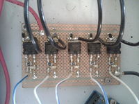
V1.1
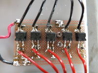
V1
The objective is a circuit board with 5 relays (electrically operated switches) that can be used for higher response performance with inductive loads (by having a freewheeling diode for each of the 5 channels) and signals activation (by having an LED for each channel).
Action Info
Unused
Action Package
Developers
Yoonseo Kang - ykang404@gmail.com

