Lathe Build
Concept
Introduction
Read this beautiful introduction on the practical aspects of a lathe in this introduction by a master of documentation, Chris Palmer - [1]
Auger
Ben,
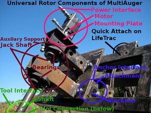
So here's my plan right now. Use a hydrauilic fixture with 20 hp that can be fixed to a table readily. This is what I have already on LifeTrac - a stiff auger mechanism:
Bill of Materials
Here is the bill of materials:
Lathe
Is it possible to convert the auger to a lathe? Sure. Take a chuck from here.
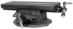
Add a slide from Enco. See review
Spec
What are the needs?
- Basic applications are couplers, hydraulic valve stems, and steam engine cylinders and pistons. Basic shortbed work on small workpieces. To be scaled up to a 2000 lb xy slide down the road for more efficient turning, with modifications as we go along.
- Length, diameter of object? 1 foot long up to 12 inch pipe
- Tolerances, including surface finish? 25 micron
- Manual or CNC? Manual at first, retrofit later.
- Material to be turned? Mild steel and aluminum.
- RPM range? 0-700 RPM
Danger
20HP at low rpm involves HUGE forces. This is going to be seriously dangerous because many of the possible failures would be catastrophic and faster than a human operator can react. Much smaller lathes cause fatal accidents from time to time. Breakage of the tool support or failure of the workholding would quite likely lead to big bits of metal flying about. Extreme caution is justified.
The proposed XY table is not intended to support anywhere near the max load that the hydraulics can apply. Most cast iron will fail fast (shatter).
A much smaller version may be a rewarding use of time to prove the design at reduced scale, cost, risk of failure, and danger of fatal or crippling injury.
Comments
- The entire system is non-optimized. It is a generalized system that optimized interchangeability of parts and multipurpose performance, not specific performance. The critical distinction is sufficiency vs. optimization. Performance can be optimized by further interchangeability. This is not a finished product, but an item that works for intended applications of milling motor couplers and boring steam engine cylinders.
- 20HP is max. It can be run from 1-20 hp.A 20 HP accident is no more fatal than a 1 HP and accident when it comes to machine vs. delicate human.
- XY table is absolutely too weak, but it is sufficient and cheap. Other suggestions are welcome.
- Marcin has significant experience regarding failure modes and behavior characteristics of hyraulics. Not an issue.
Materials, Rigidity
Pro lathes are usually made of the fewest thickest possible pieces of cast iron, for rigidity and damping. If mild steel box and sheet, bolted or welded, was good enough then there would probably be examples out there (If it's easy and cheaper and the Chinese won't do it then it probably doesn't work). There are substantial risks that the lathe will work poorly or not at all unless it is small and made of very thick stock. If any machine tool is insufficiently rigid then the cutting edge chatters on the work piece, giving a bad finish, rapid heating of the tool, and rapid tool failure. Also, cutting forces cause the machine to elastically distort, quickly introducing very large errors.
Without defining the spec, it is difficult to design. Materials for machine tool frames include
- Aluminium alloy, on small cheap low precision or soft material tools
- Cast Iron, on most machines. Well proven.
- Synthetic or real Granite, on super precision moderate mechanical load machinery
Synthetic granite is made from ~80% granite powder with an epoxy binder, and has ~9x better damping than cast iron but much lower tensile strength. (I'd like to experiment with machine tools made from a synthetic granite modified with chopped strand carbon fibre, but that's an unproven material. Leo.dearden)
Synthetic Granite
- What are costs of raw materials?
- Where do we get them?
Cross Slide
- What are options for an off-shelf cross slide?
- What are accuracy limits of simple cross slides made from cold rolled steel, 3/4 inch fine nuts and bolts, where nuts are pretensioned to minimize backlash? Is this a simple, robust solution that can reduce backlash to 25 microns?
- Are there any good DIY solutions for precision cross slides?
Collaborators
Review
Sam Putnam
First comment would be that you're proposing to build a Type 1 replicator, which can be set up with additional jigs and fixtures for Type 2 replication. :-)
Second comment would be this:
That's a 19-year-old CNC lathe for a hundred bucks. Granted that it was probably broken, but a broken lathe is almost always a much simpler and cheaper platform than a brand-new lathe. If you watch ebay long enough, you will find another.
Now, you probably need a lathe pretty badly regardless, and a Type 3 lathe is a CNC screw machine with quick-change tool head and workpiece feed at a bare minimum, so there's no reason you shouldn't get or develop yourself a Type 1 lathe for Factor E. It would be awesome if such a design incorporated the idea of eventually adding enough modular components that the lathe would qualify as a CNC screw machine.
Moving on to the design you've shown. It's not especially specific but I see several things that concern me. One is that you seem to be coupling your hydraulic motor directly to the spindle and headstock. Normally one isolates the motor with a pulley to prevent vibration from traveling along the shaft. That's easy enough to fix.
The poured-concrete bed will shrink on you, but you can compensate for that effect with gibs. Does your design have gibs? I couldn't tell. Using a single piece of round stock as a ways is going to enthusiastically bugger your accuracy as soon as you go off center, and possibly send the toolpost flying. Would you consider a couple pieces of round stock or T-slot instead? An extruded ways will probably be simpler/cheaper than cold-rolled steel or scraped bronze or cast iron, and it matches our emerging design pattern language.
BTW a design based on a cast concrete bed isn't maximally portable. Some of us live in subduction zones and high Richter events have a way of cracking monolithic concrete!
For good generality in a CNC lathe, one needs travel along the carriage and cross-slide, plus rotation of the tool angle, making for two Cartesian coordinates and one polar. The carriage and cross slide can be simple lead-screw drives and rotary tables are usually built with a worm drive. If one wants milling capacity on the same machine, a Z axis is needed, but for a Type 3 lathe there are two additional fittings (at least): a robot that feeds workpieces into the chuck and a quick-change toolhead. That would make it inconvenient to mill on the same machine one lathes with; it is widely said to be inconvenient in any case. A mill spins the toolhead while a lathe spins the workpiece: the two tasks are different enough to benefit greatly from two dedicated machines.
Concluding comment would be: work with the OpenLathe people, they know a whole hell of a lot. If you join the googlegroup you'll have access to a grip of files with a ton of revelant and useful information. Hope this helps.
Ben Lipkowitz
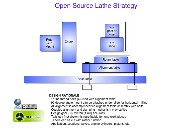
the rotary table is silly. you ain't gonna need it. the tool post has to be below the centerline, and the rotary table eats up valuable vertical distance.
you should use three points for alignment instead of four. don't make me crawl under the table to loosen the bolts; they should thread into nuts welded under the table and be locked with jamb nuts on the top side. actually, shims would be better: more rigid and compact.
i hope your "base table" is thicker than the two inches in the above diagram. a plain steel bed won't work because it has no damping, and sam doesn't like concrete for some reason (earthquakes, really?) so how about "polymer concrete" - just epoxy mixed with granite aggregate and powder. "it's what the pro's use." anyway, concrete machine tools were very common during WWII and during reconstruction in germany. they can be quite beautiful actually: http://www.epucret.de/en/products-solutions/product-overview/cast-parts/ http://www.epucret.de/en/products-solutions/product-overview/accuracy/
if i were building a huge lathe to be portable, i'd use a big rectangular tube of structural steel and pack it full of gravel and something viscous like wet bentonite clay or heavy oil.
the original "guide rail" is awful, and two of them would be only slightly less awful. you need full support under the carriage at every point along its travel. that floating bar will flex like mad in the center. for most CNC tasks you tend to do small stuff, so the little XY table might be sufficient on its own, bolted directly to the bed, then unbolted and moved around for doing bigger stuff. speaking of CNC, one huge problem is that there's no spindle through hole, so you can't use a bar feeder.
if you're going to be doing end milling with the angle plate, make sure to size the carriage much wider than it needs to be for lathe work, at least twice as wide as the distance from bed to centerline. also, it has to be mounted to the top side of the XY table.
I suggest making some toy models out of wood or foam or whatever you have lying around.


