D3D Fusion Printer Conceptual Design
Jump to navigation
Jump to search
This document lists D3D Printer Design decisions and reasoning behind them in chronological order. The intention is to make the process as debuggable as possible and facilitate later creation of formal documents such as Design Decision Tree and Conceptual Design diagrams. It follows the D3D_Design_Methodology.
Sources Driving Design Desicions in Priority Order
- D3D_Fusion_printer_design#Higher_Level_Goals
- D3D_Fusion_printer_design#Desired_Attributes
- D3D_Fusion_printer_design#Functional_Requirements
- RepRap Interface Standard
- The shape of the input determines the shape of the design and tests.[1]
3D Printer Signature
Input: Power, Build material, Supporting surface(s), Instructions Output: Physical object
Purpose Statement
A 3D printer is a machine that synthesizes build material into 3D objects according to a series of pre-determined instructions.
Examples
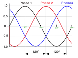
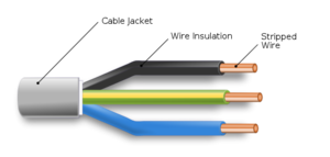
We will assume that a mains voltage will power the 3D printer, with the constant shape:


For the build material, we will assume filaments behaving roughly as thermoplastics with the constant shape: ...
Being Creative
Shape of Inputs
Build Material
We expect
- ↑ Cite error: Invalid
<ref>tag; no text was provided for refs namedhtdp