Uploads by Cabeza de Pomelo
Jump to navigation
Jump to search
This special page shows all uploaded files.
| Date | Name | Thumbnail | Size | Description | Versions |
|---|---|---|---|---|---|
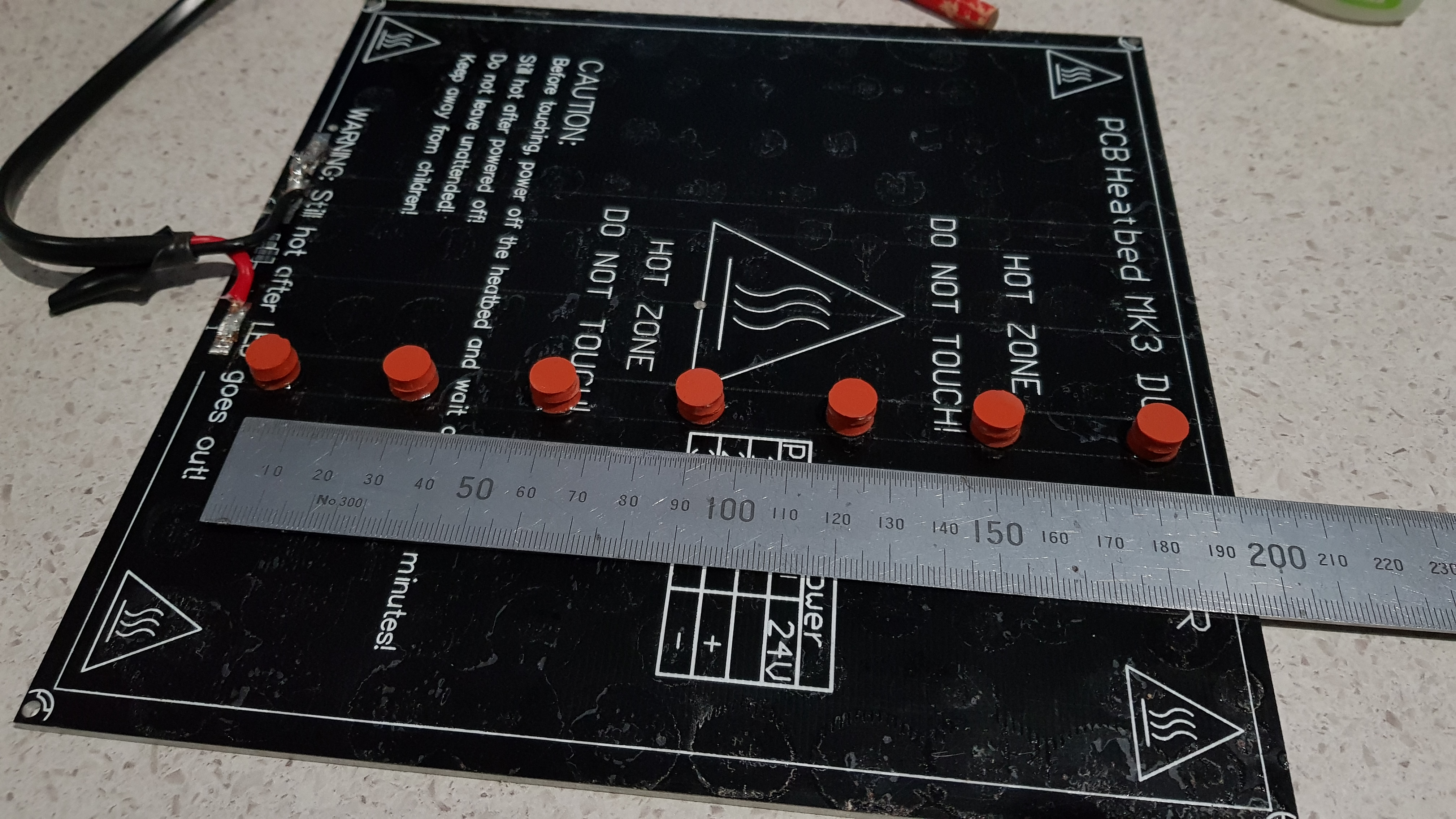
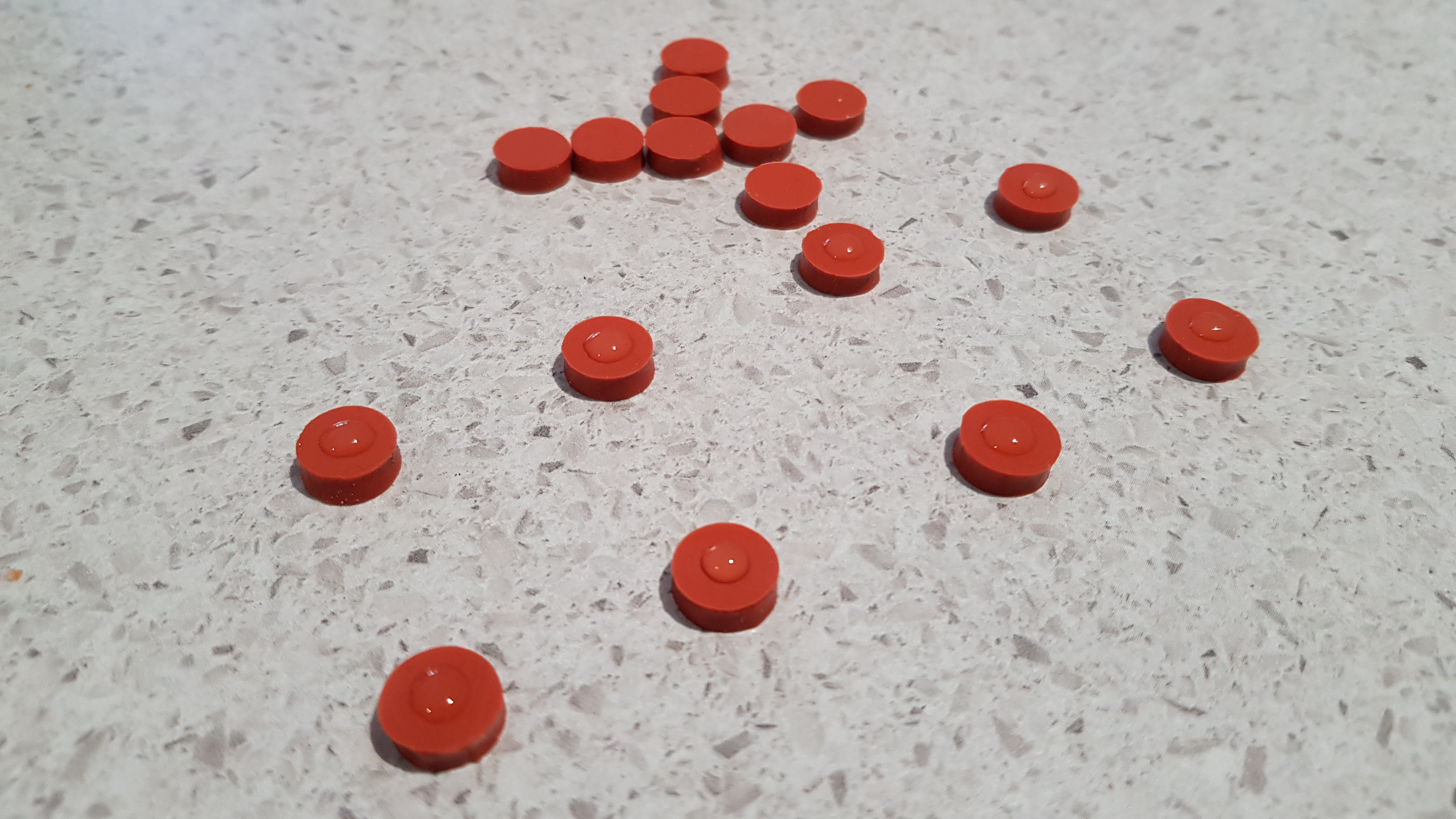
| 10:56, 9 January 2018 | Rubber spacers01.jpg (file) | 3.08 MB | Spacers glued to HBP. | 1 | |
| 10:54, 9 January 2018 | Rubber spacers00.jpg (file) | 2.85 MB | Doubling the thickness. | 1 | |
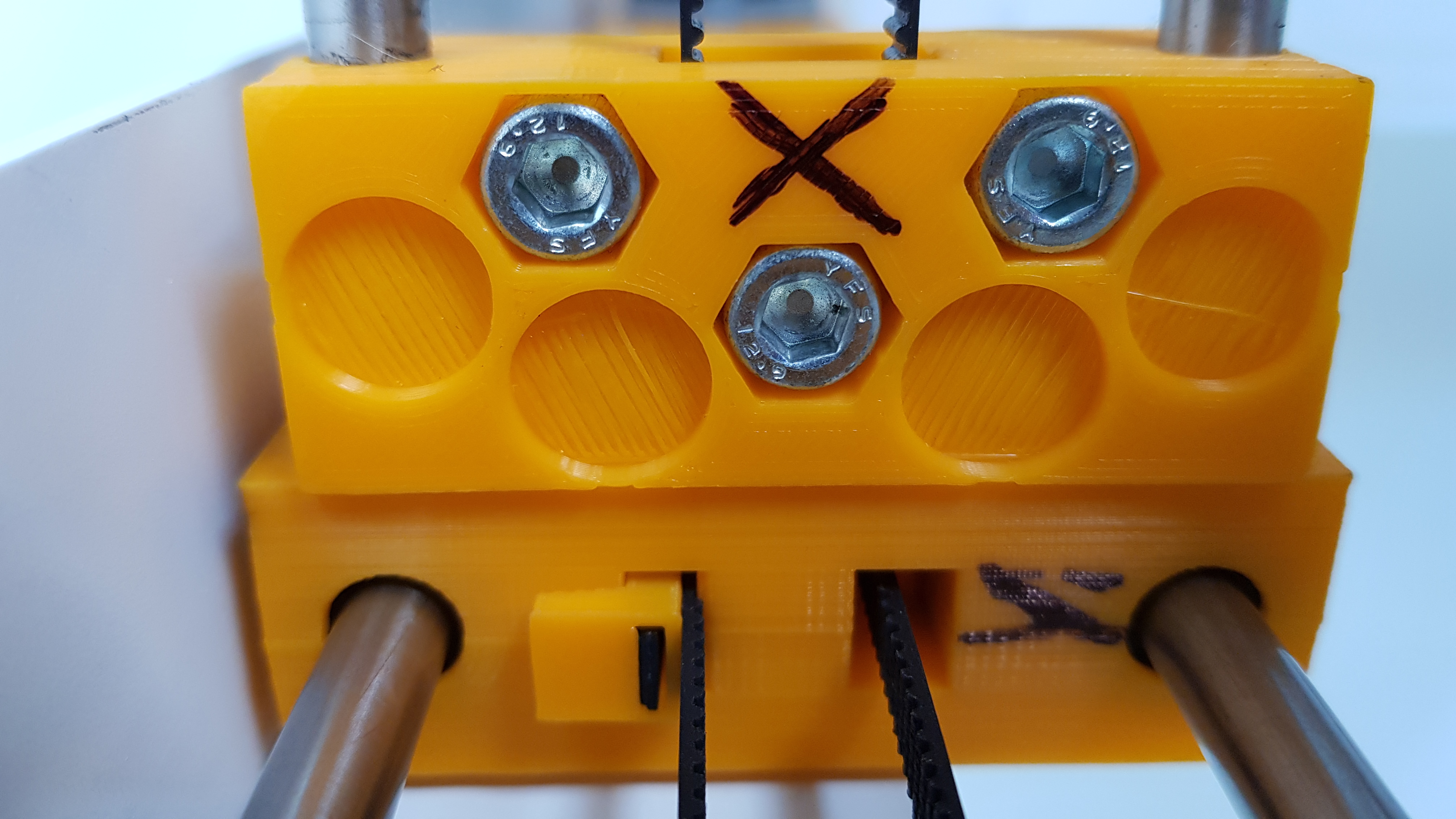
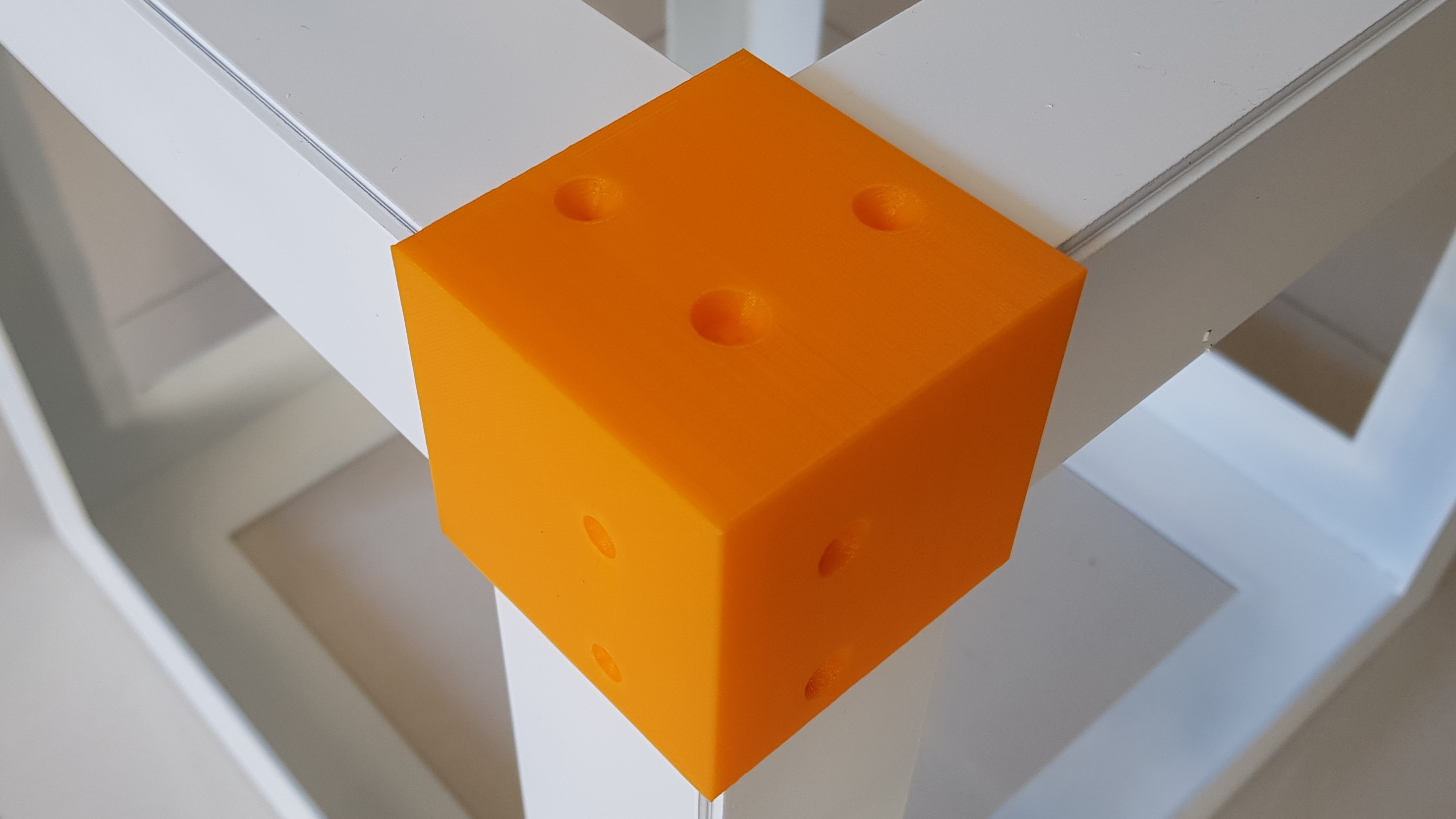
| 10:44, 9 January 2018 | Y1 x square.jpg (file) |  |
2.52 MB | Square mating of carriage of Y1 and short idler side of X. | 1 |
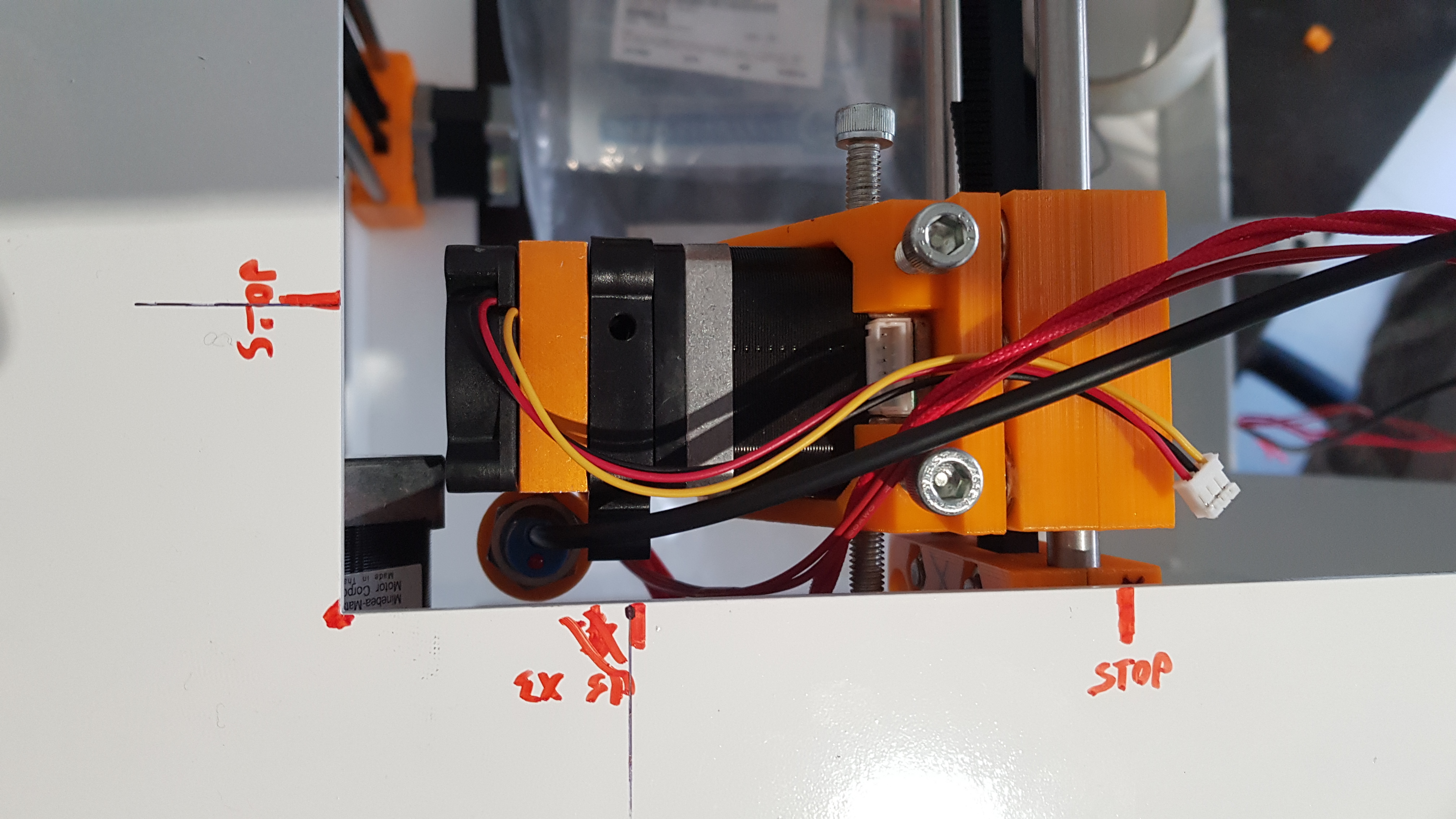
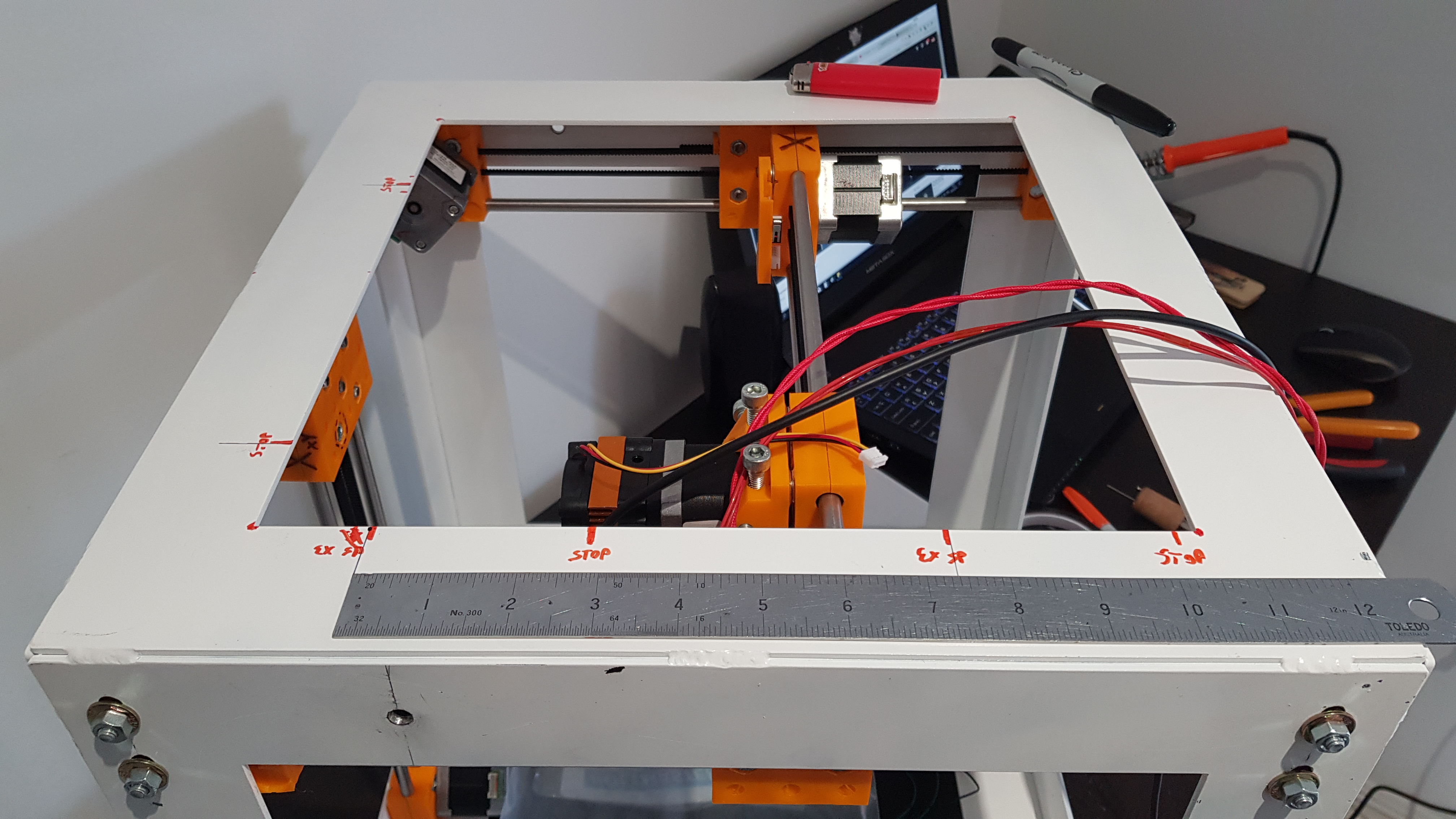
| 10:40, 9 January 2018 | End stop y modified.jpg (file) |  |
2.32 MB | Extension added on Y1 carriage to stop X before extruder hits Y1 motor. By doing this travel range on X is increased by 10mm. | 1 |
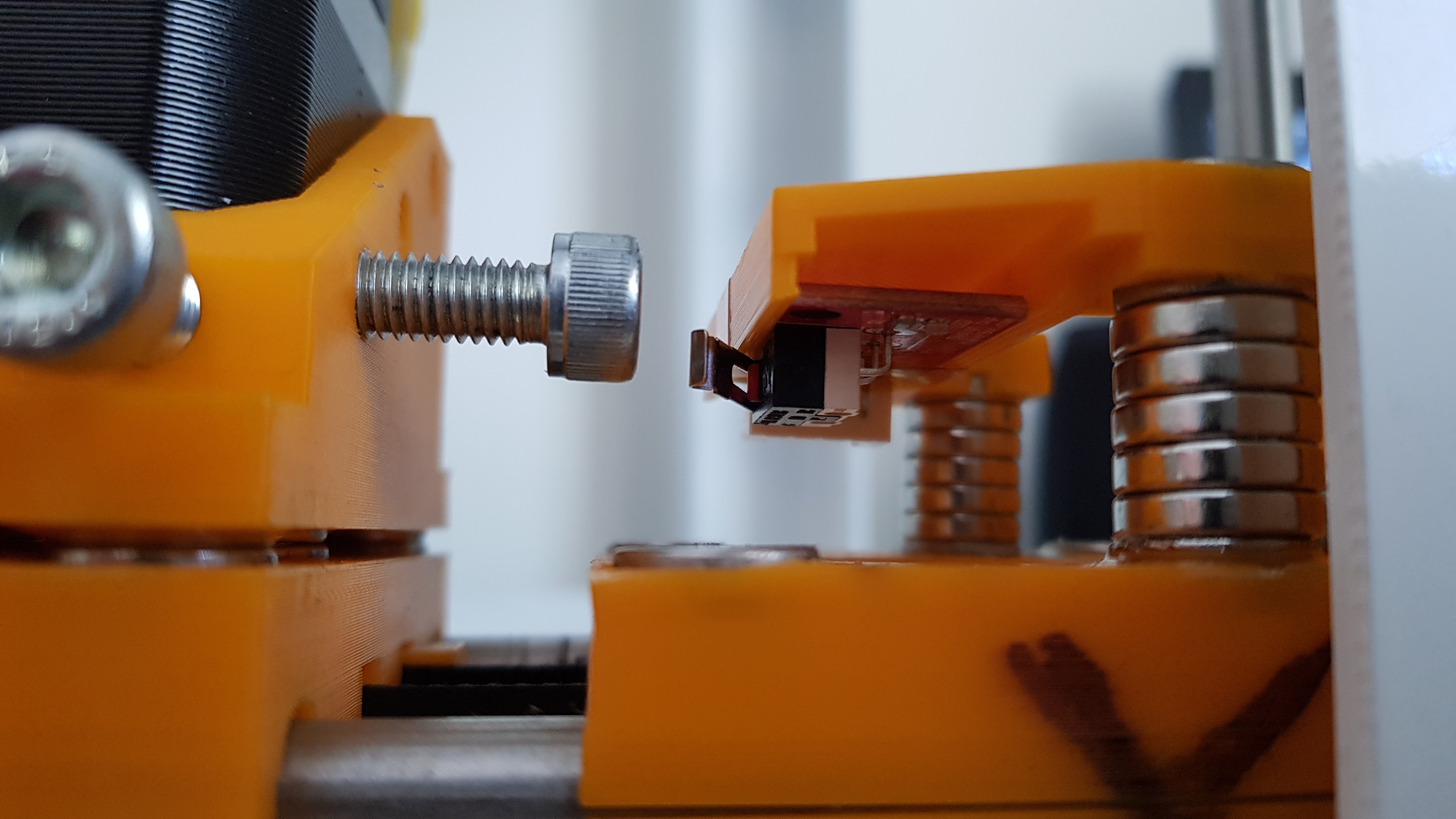
| 10:36, 9 January 2018 | End stop x modified.jpg (file) |  |
2.59 MB | Modified end stop on X to increase travel range. | 1 |
| 10:22, 9 January 2018 | X axis parallel.jpg (file) |  |
2.58 MB | Checking that x-axis is parallel to frame after installation. | 1 |
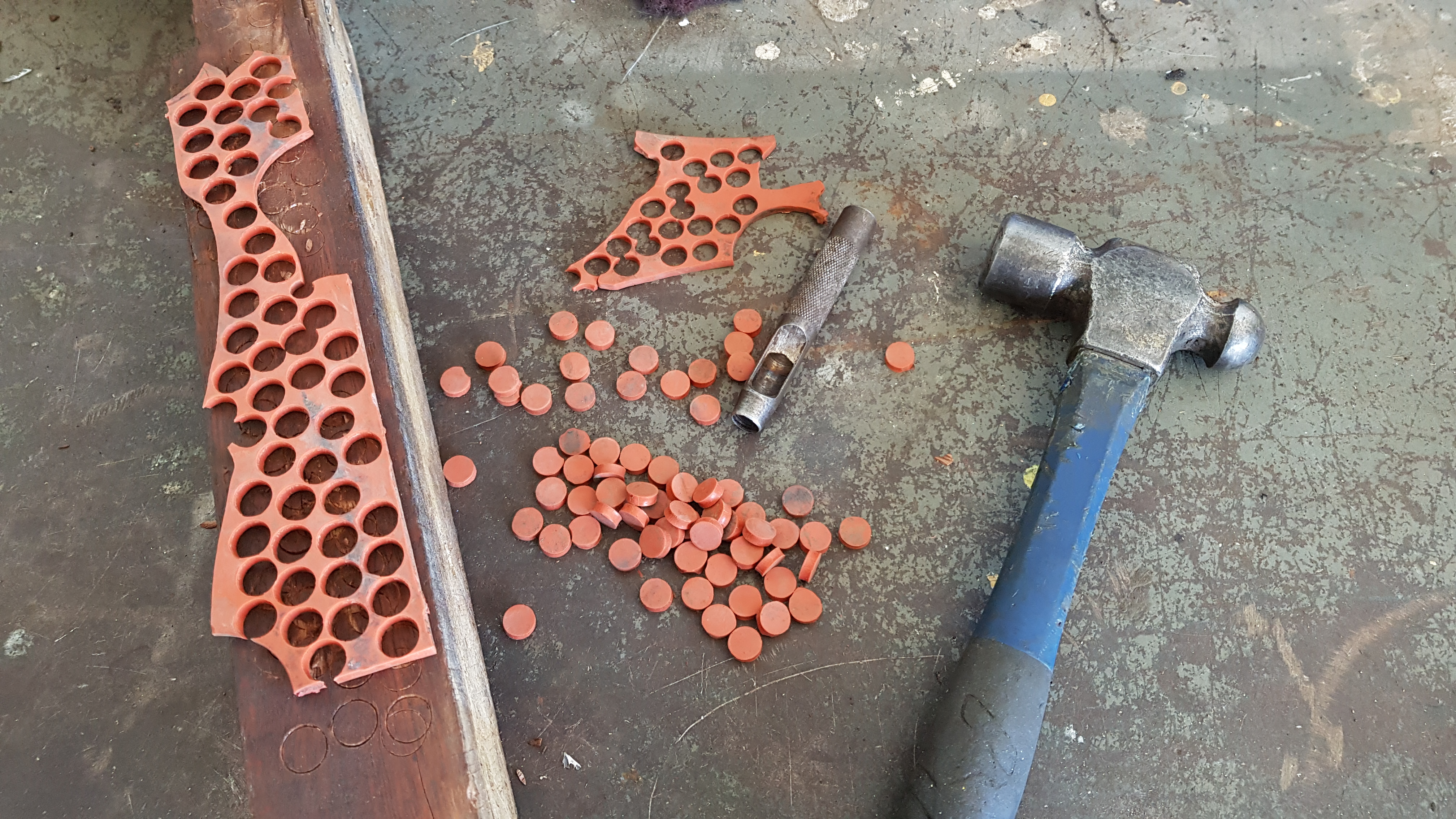
| 10:20, 9 January 2018 | Rubber spacers.jpg (file) | 4.12 MB | Heat resistant rubber spacers for heated bed. | 1 | |
| 05:49, 6 January 2018 | Clearance Y1 X.jpg (file) | 2.75 MB | Clearance in the Y1-X corner | 1 | |
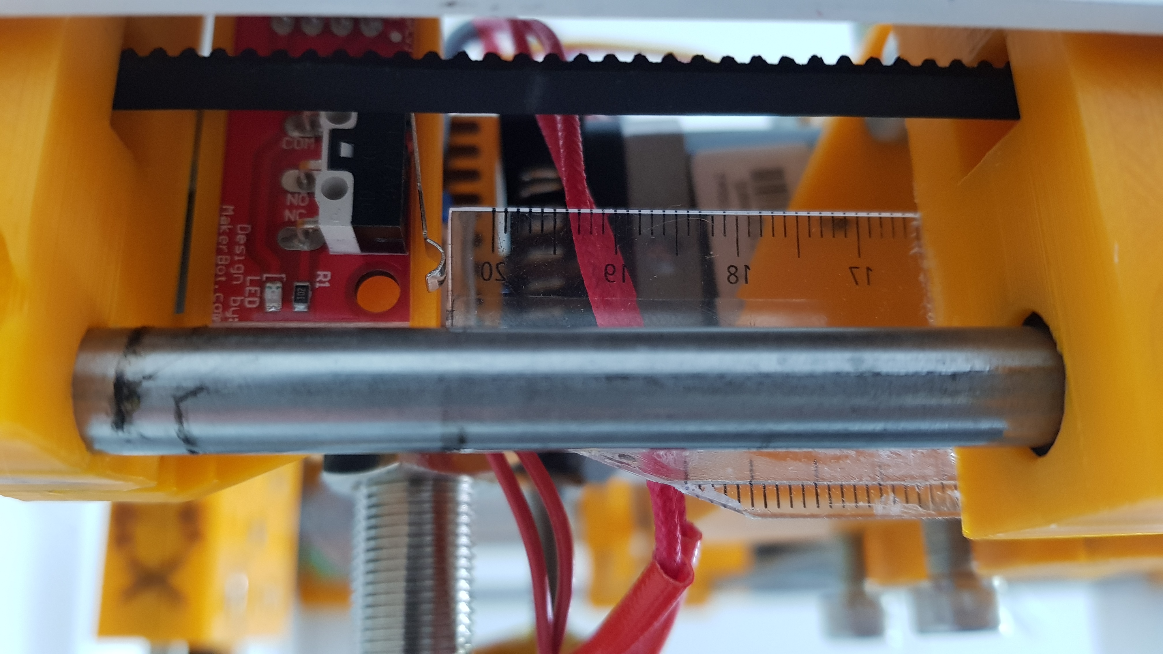
| 05:46, 6 January 2018 | Range y.jpg (file) |  |
2.75 MB | Range of movement on Y-axis. 188mm | 1 |
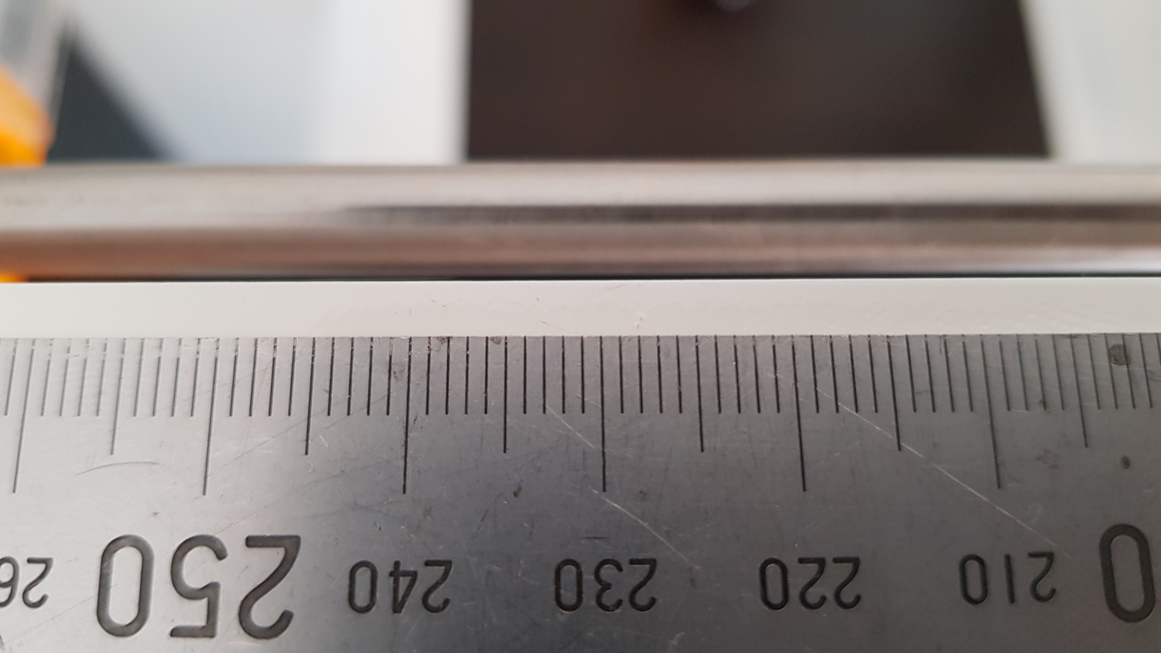
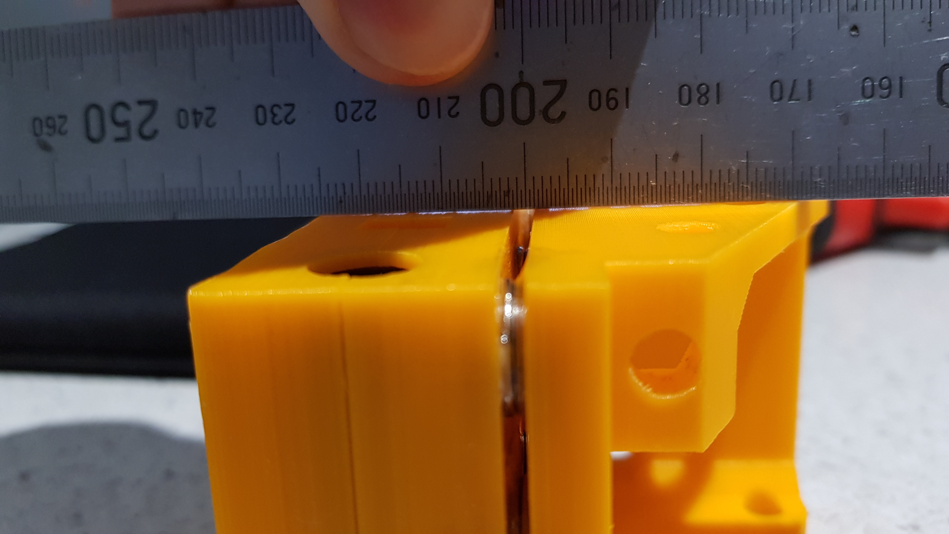
| 05:45, 6 January 2018 | Range X.jpg (file) |  |
2.87 MB | Range of movement on X-axis. 191 mm | 1 |
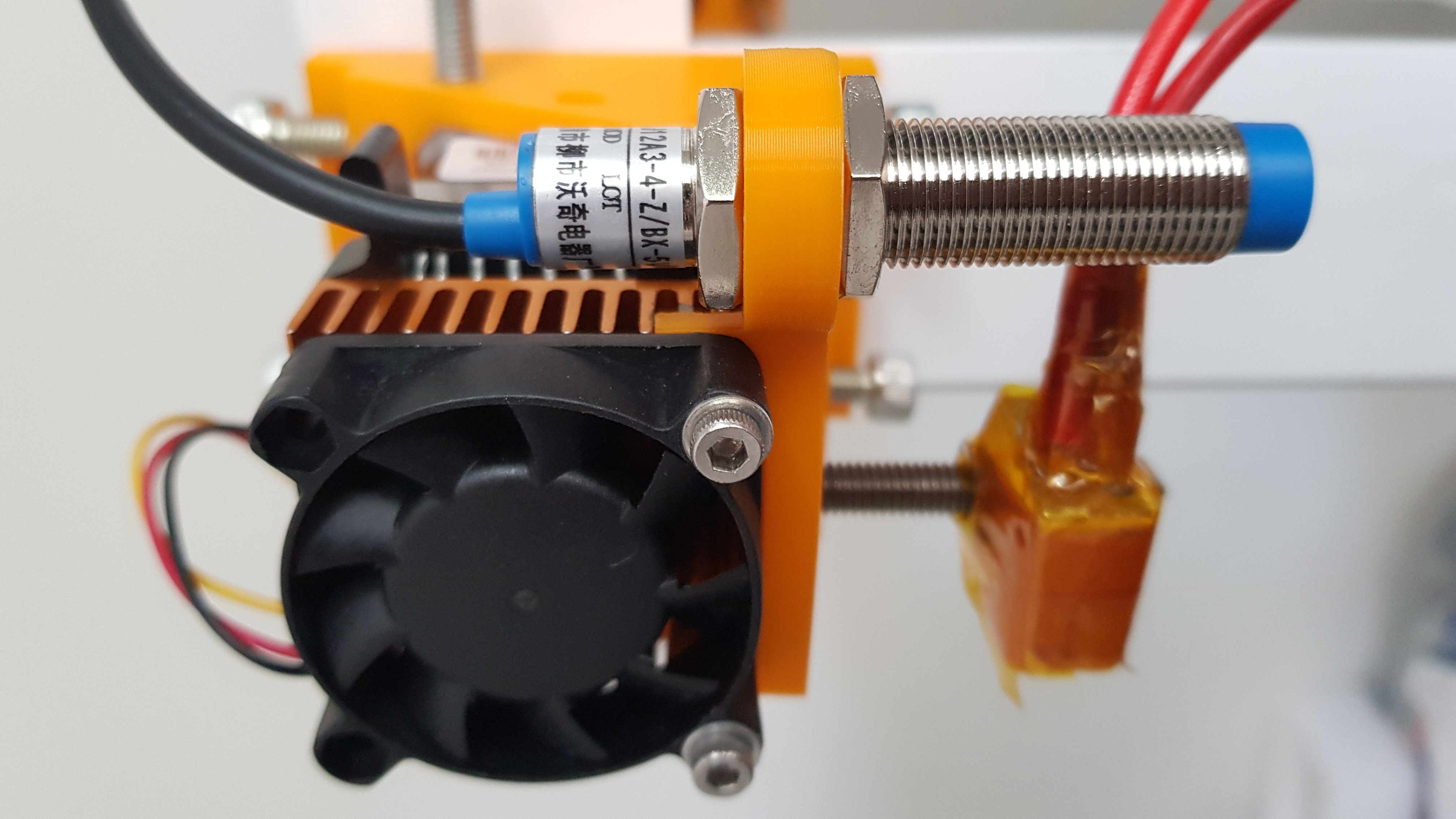
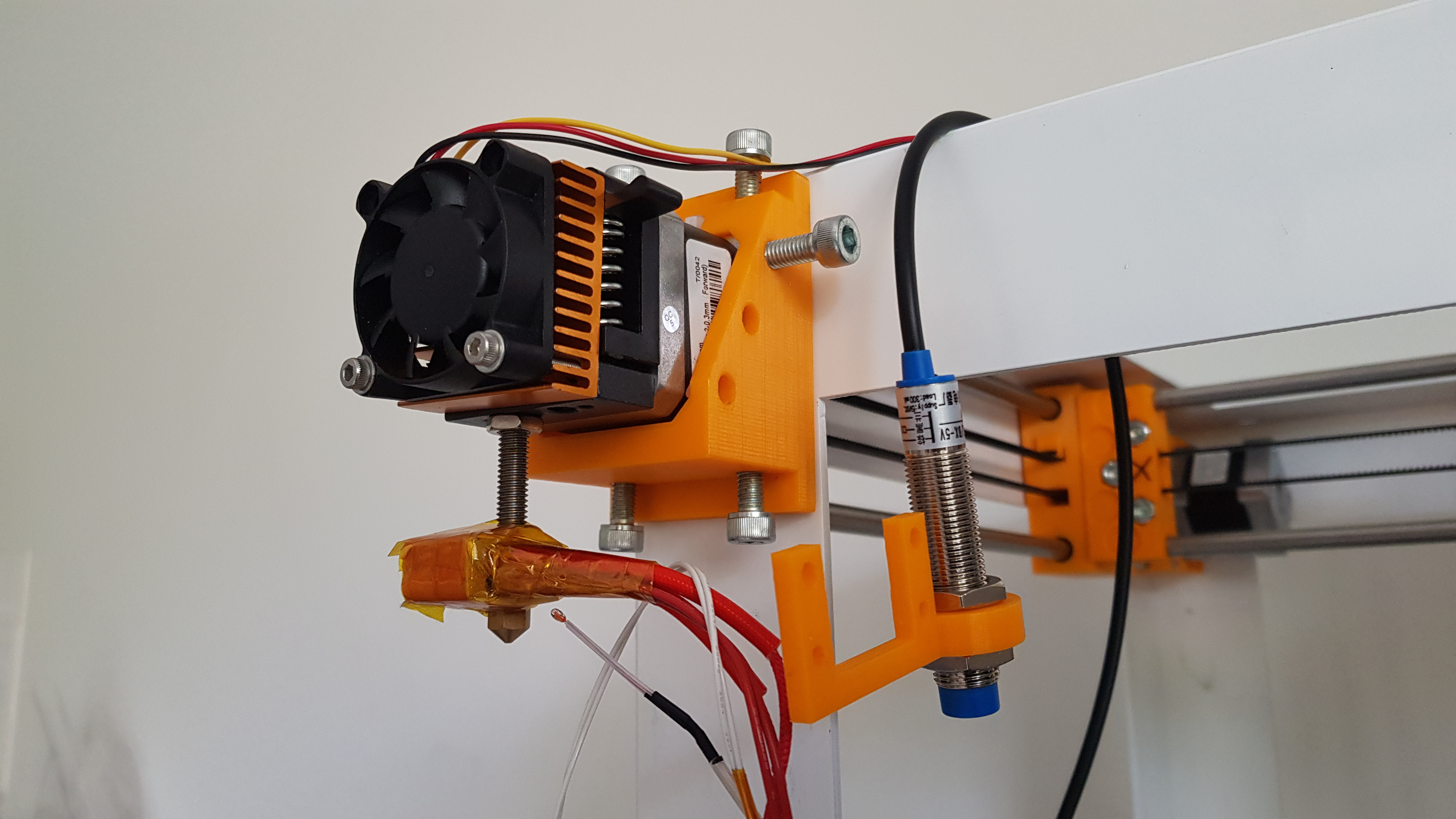
| 05:42, 6 January 2018 | Sensor on.jpg (file) |  |
2.75 MB | Inductive sensor in place. | 1 |
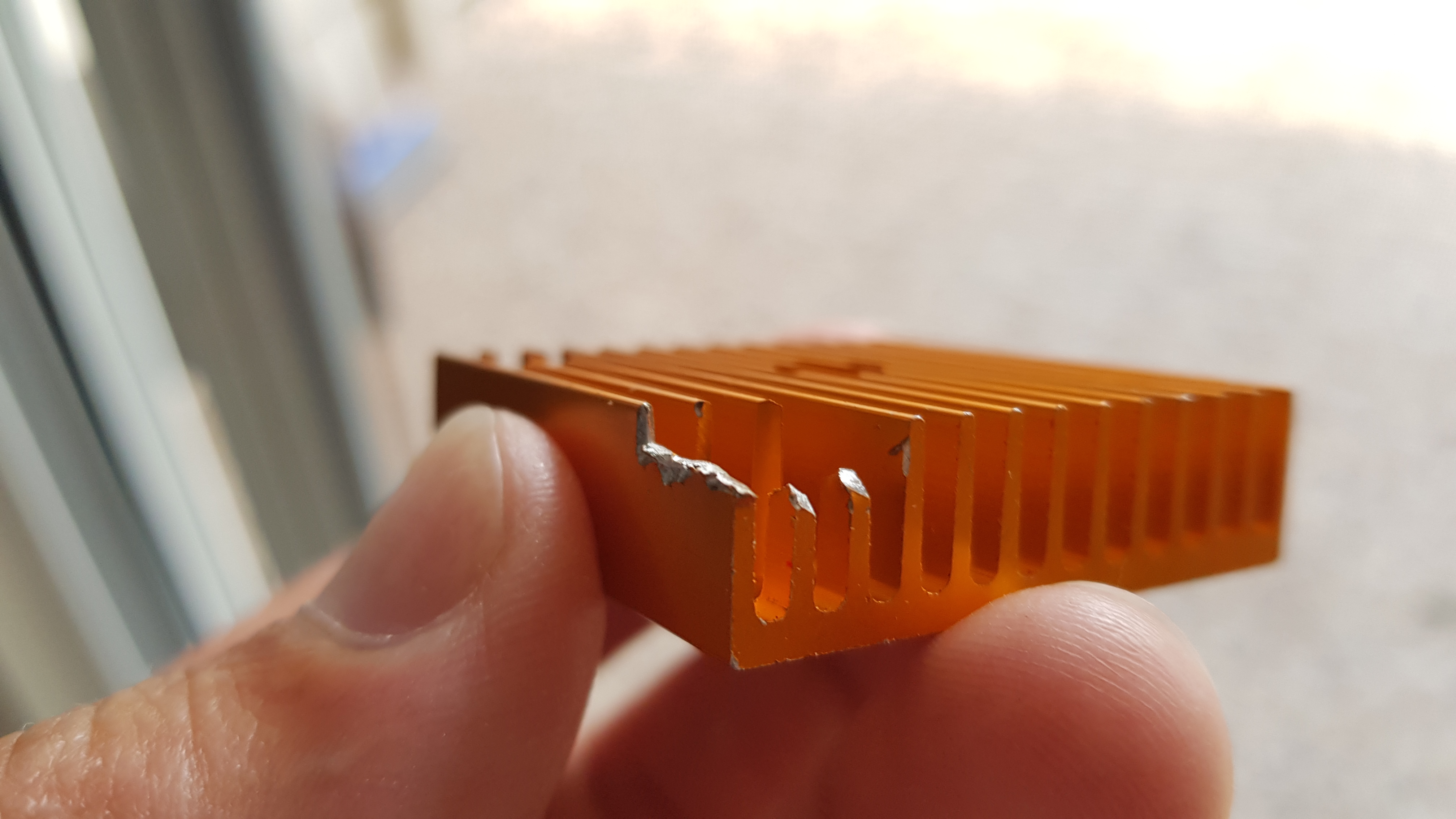
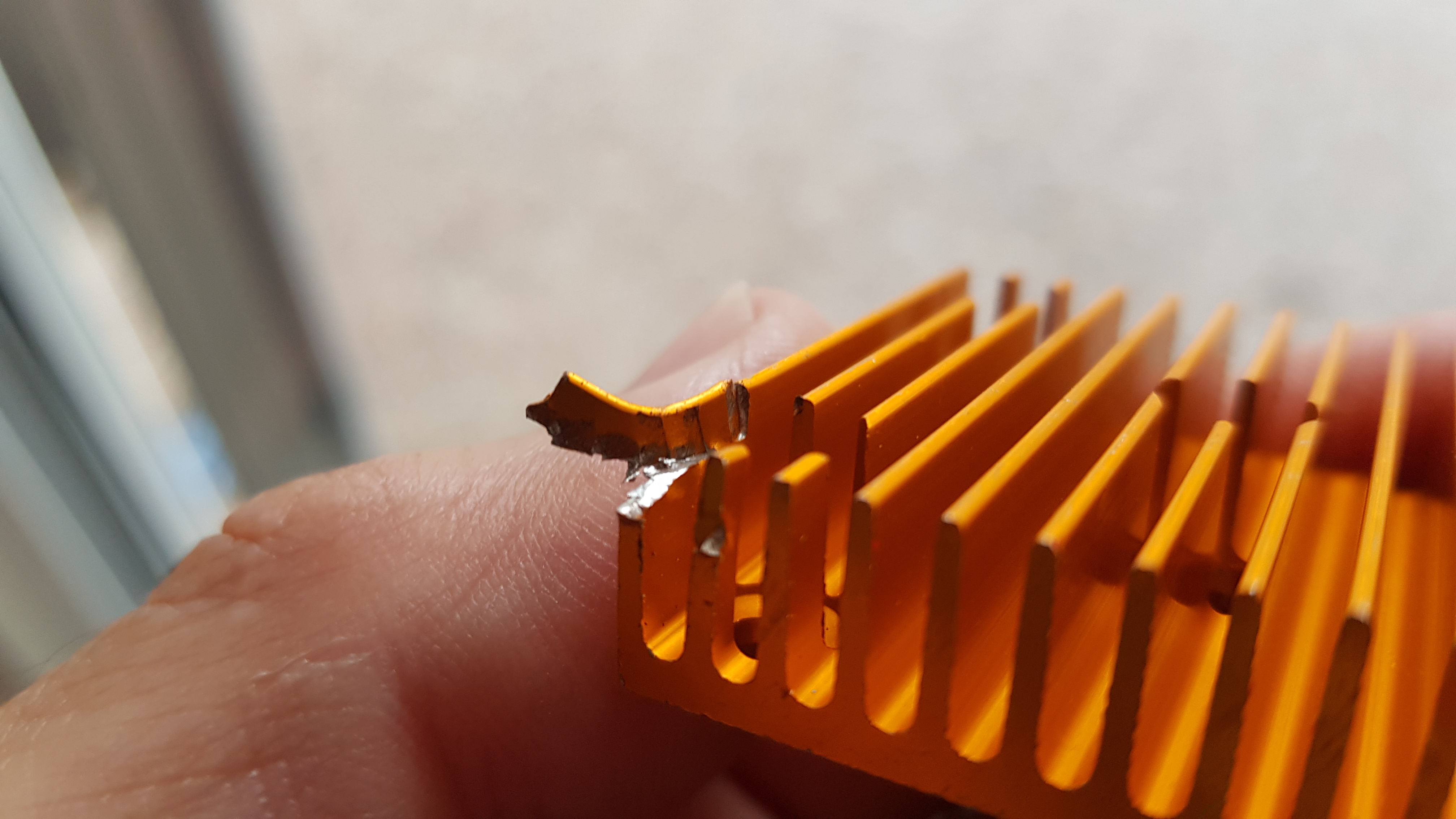
| 05:40, 6 January 2018 | Heat sink ext01.jpg (file) |  |
1.98 MB | Vanes | 1 |
| 05:38, 6 January 2018 | Heat sink ext00.jpg (file) |  |
2.08 MB | Trimmed extruder heat sink | 1 |
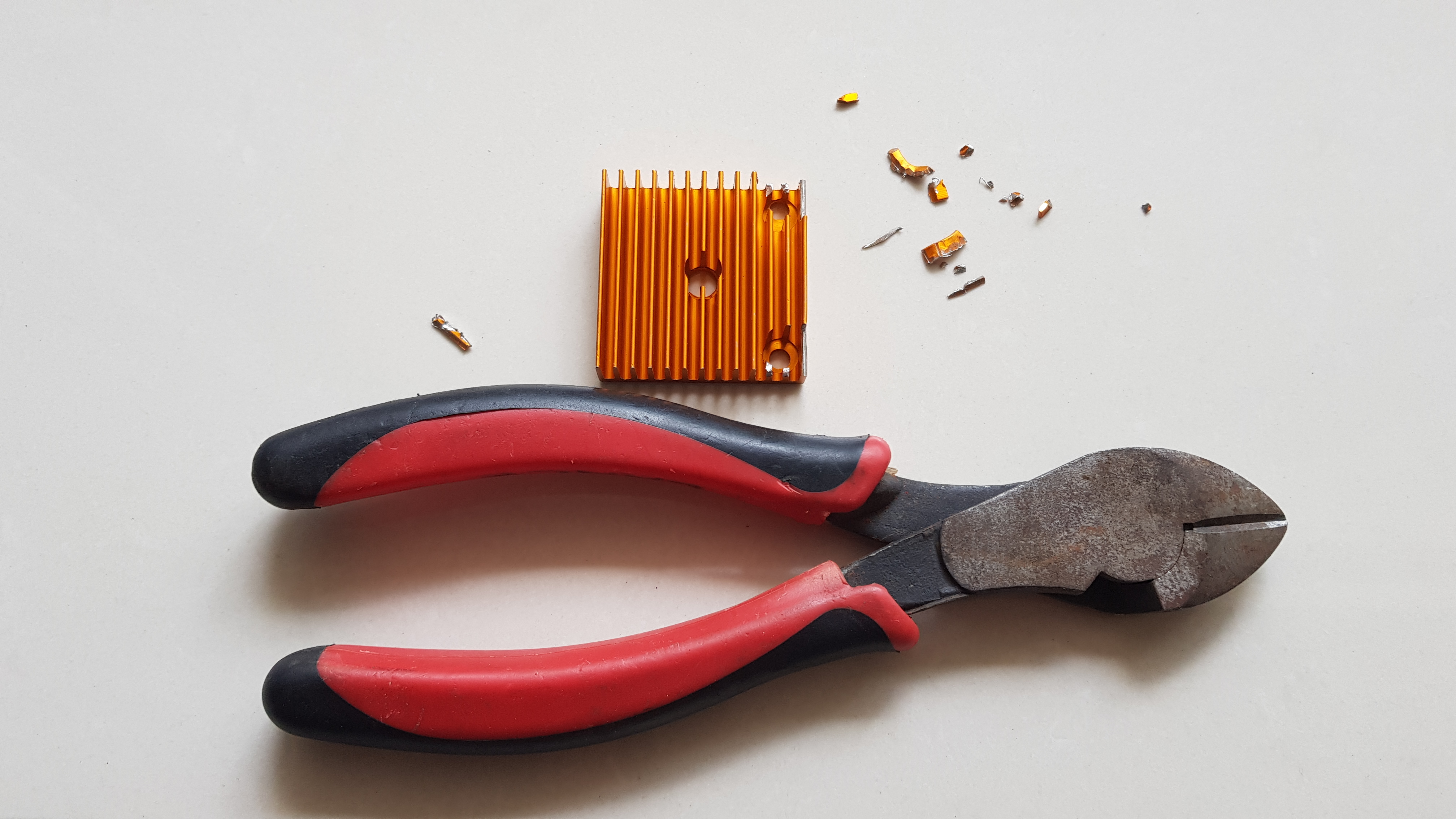
| 05:37, 6 January 2018 | Heat sink ext.jpg (file) |  |
2.23 MB | Trimming extruder heat sink | 1 |
| 05:34, 6 January 2018 | Inductive install.jpg (file) |  |
2.66 MB | Installing inductive sensor | 1 |
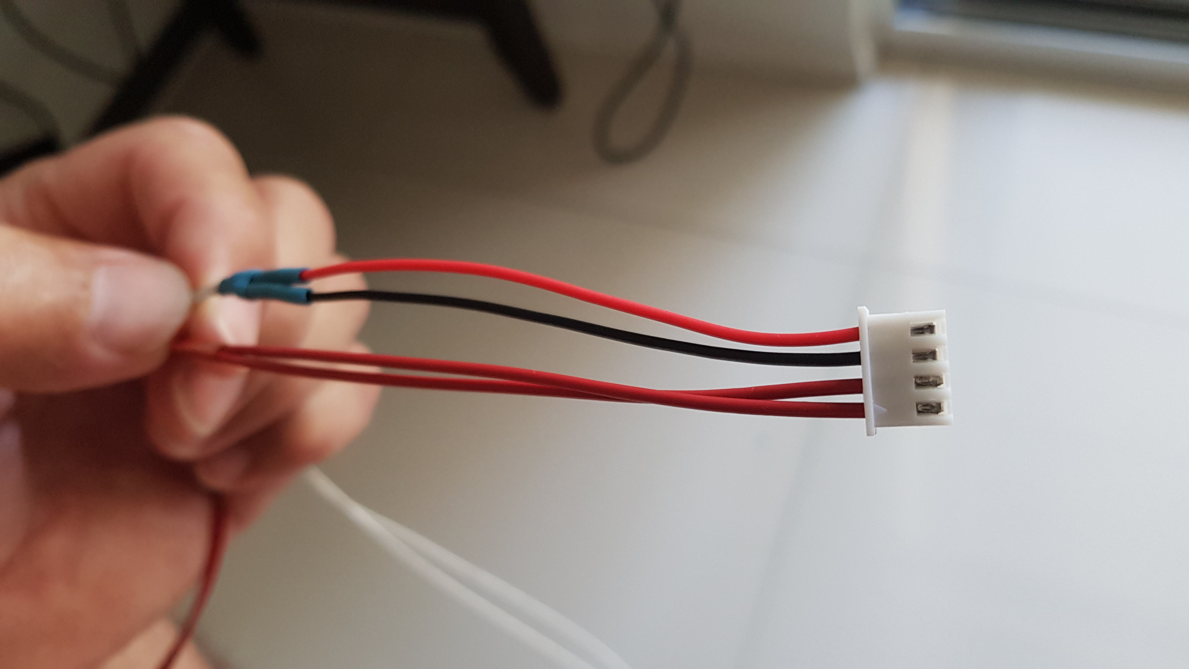
| 05:31, 6 January 2018 | Termistor connector.jpg (file) |  |
2.34 MB | EO and HBP termistors in one connector. Recycle. | 1 |
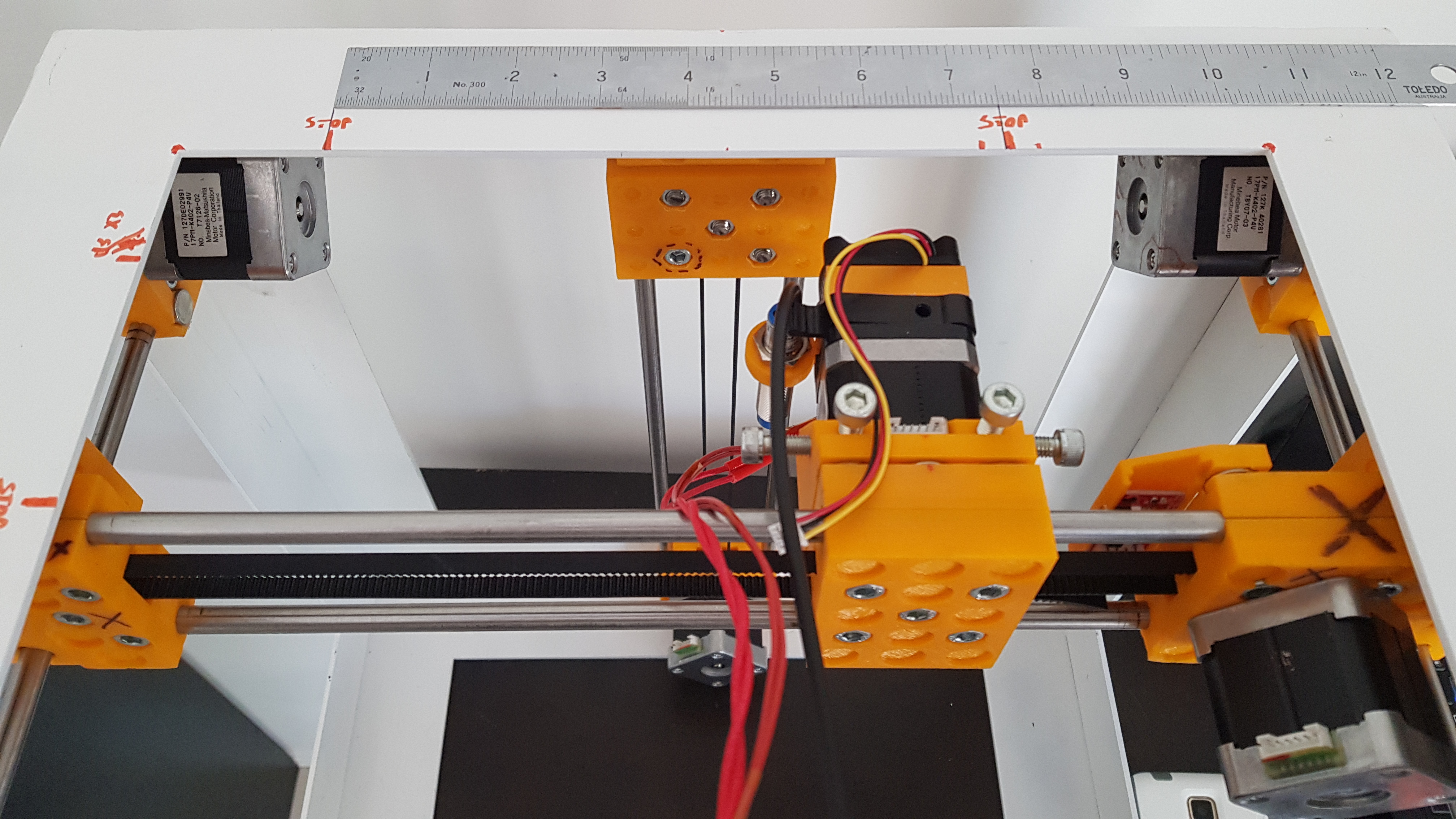
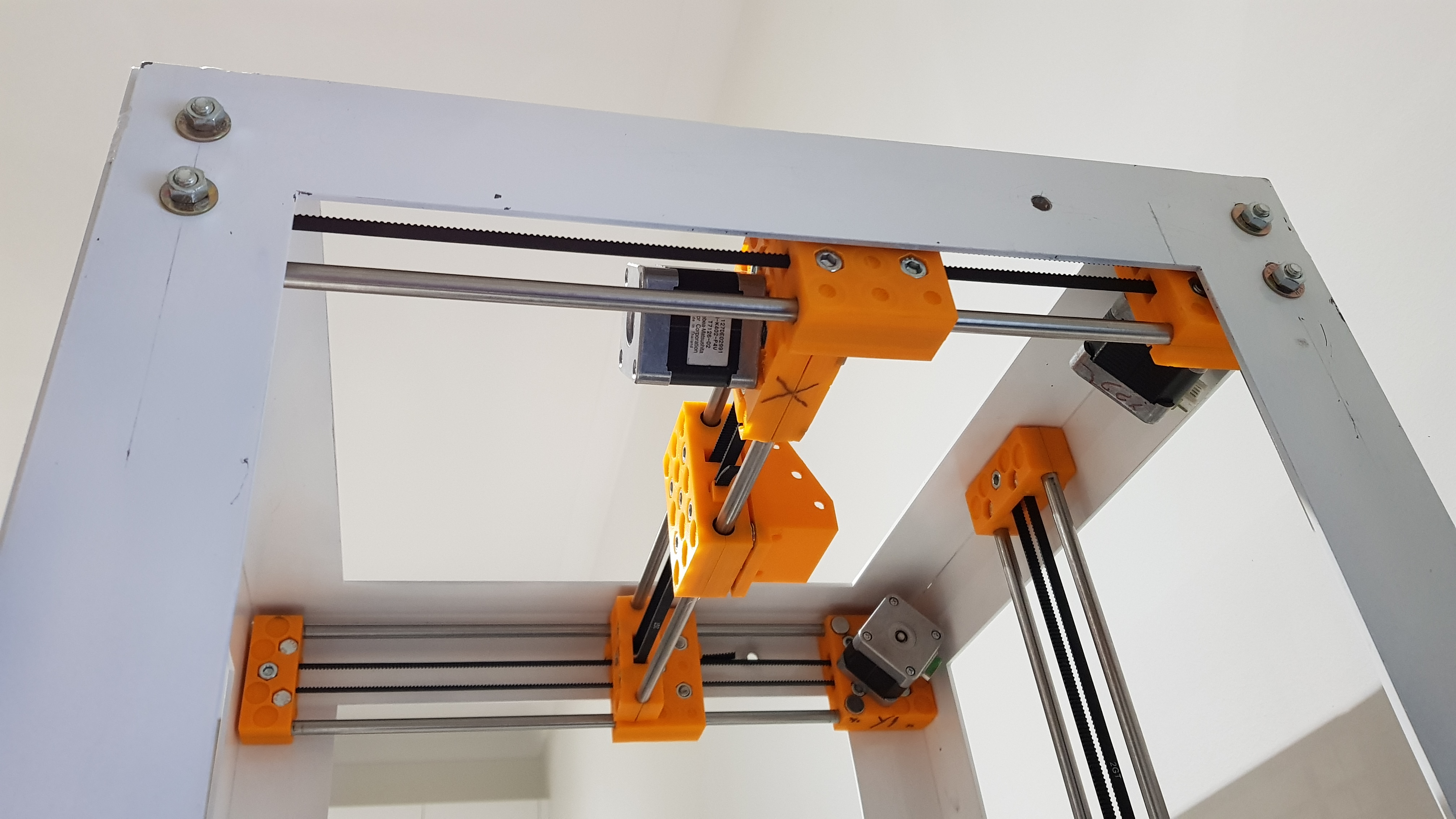
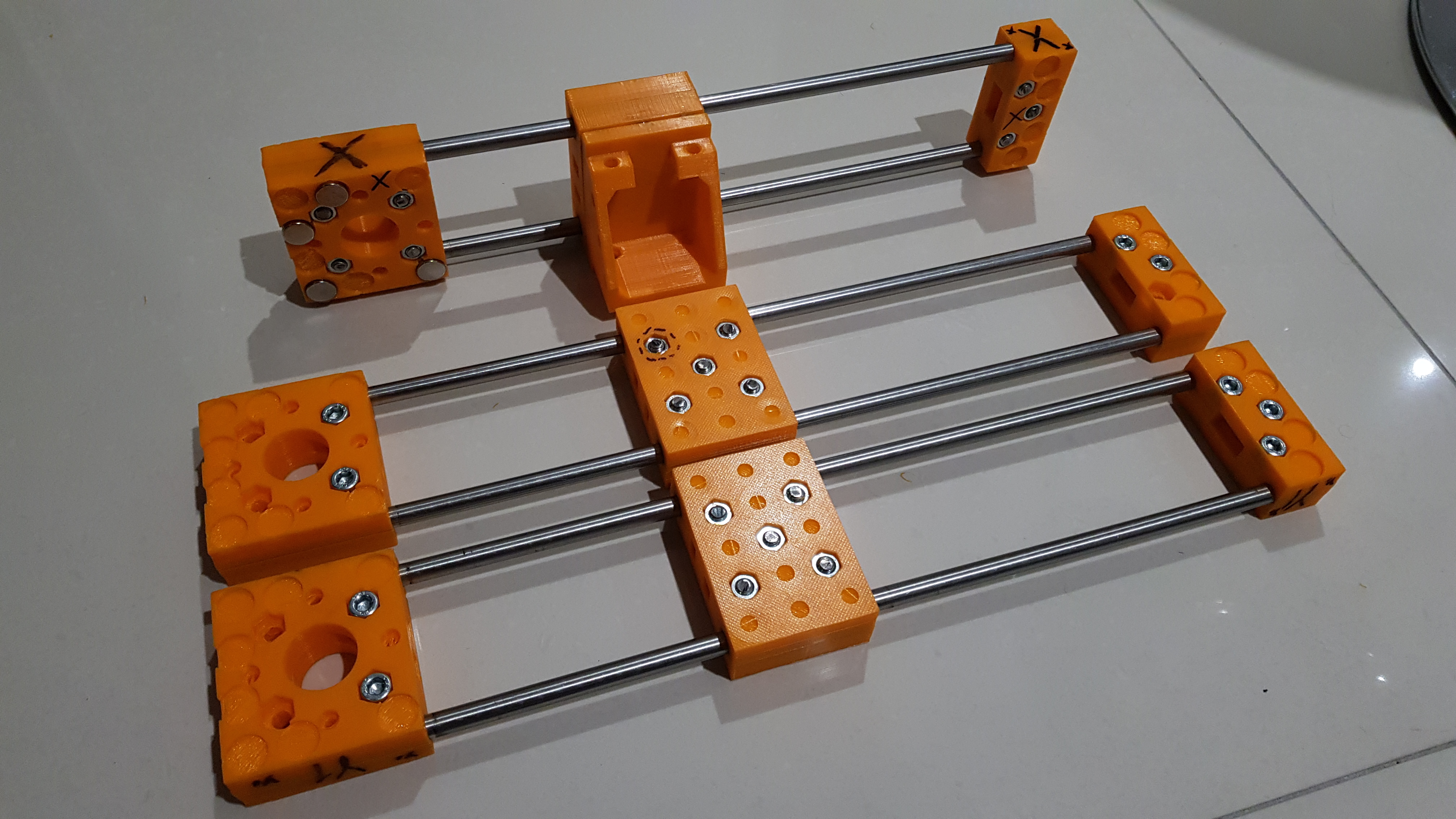
| 05:23, 6 January 2018 | Axes configuration.jpg (file) |  |
2.28 MB | Positions of axes and motors. | 1 |
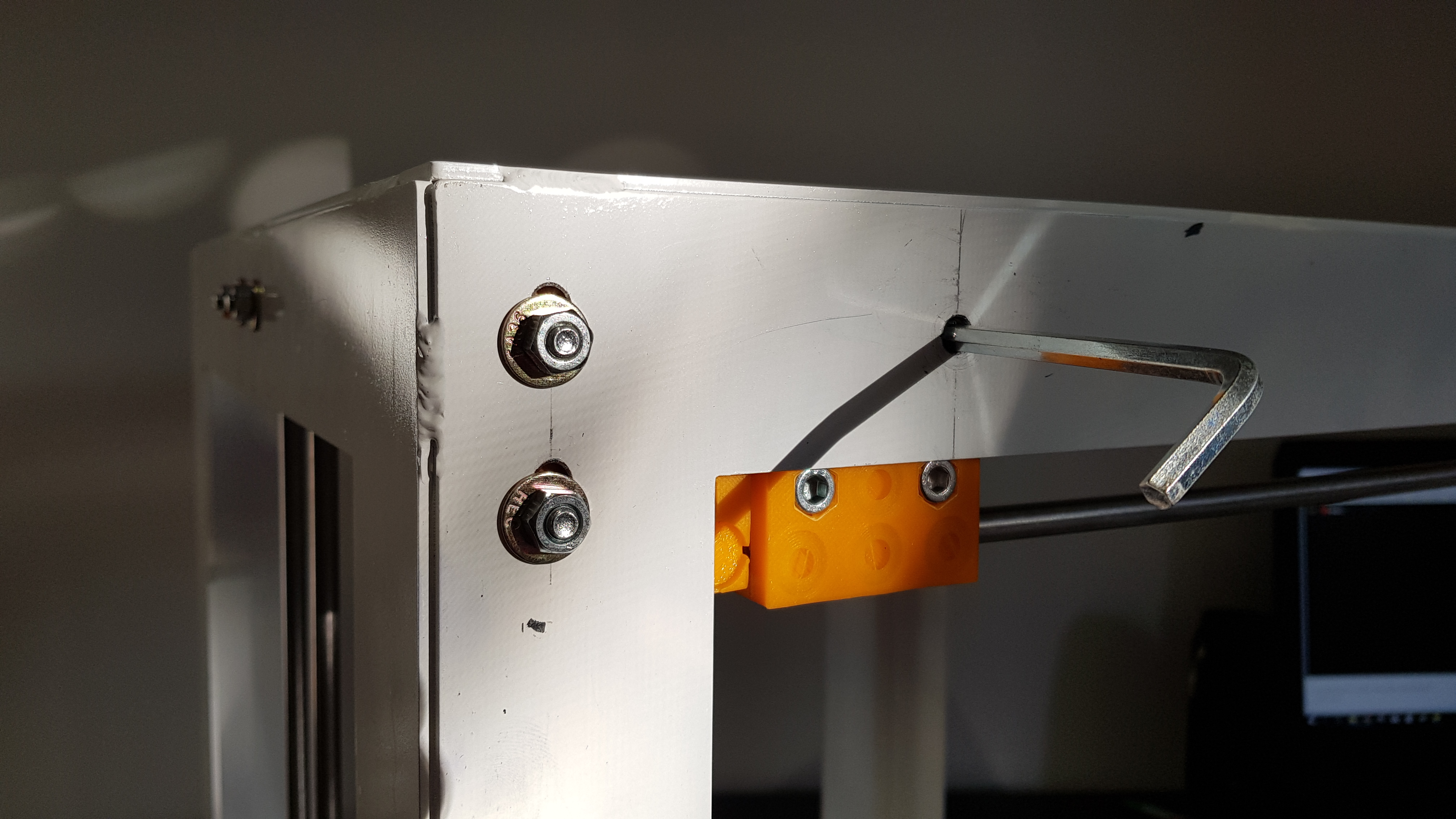
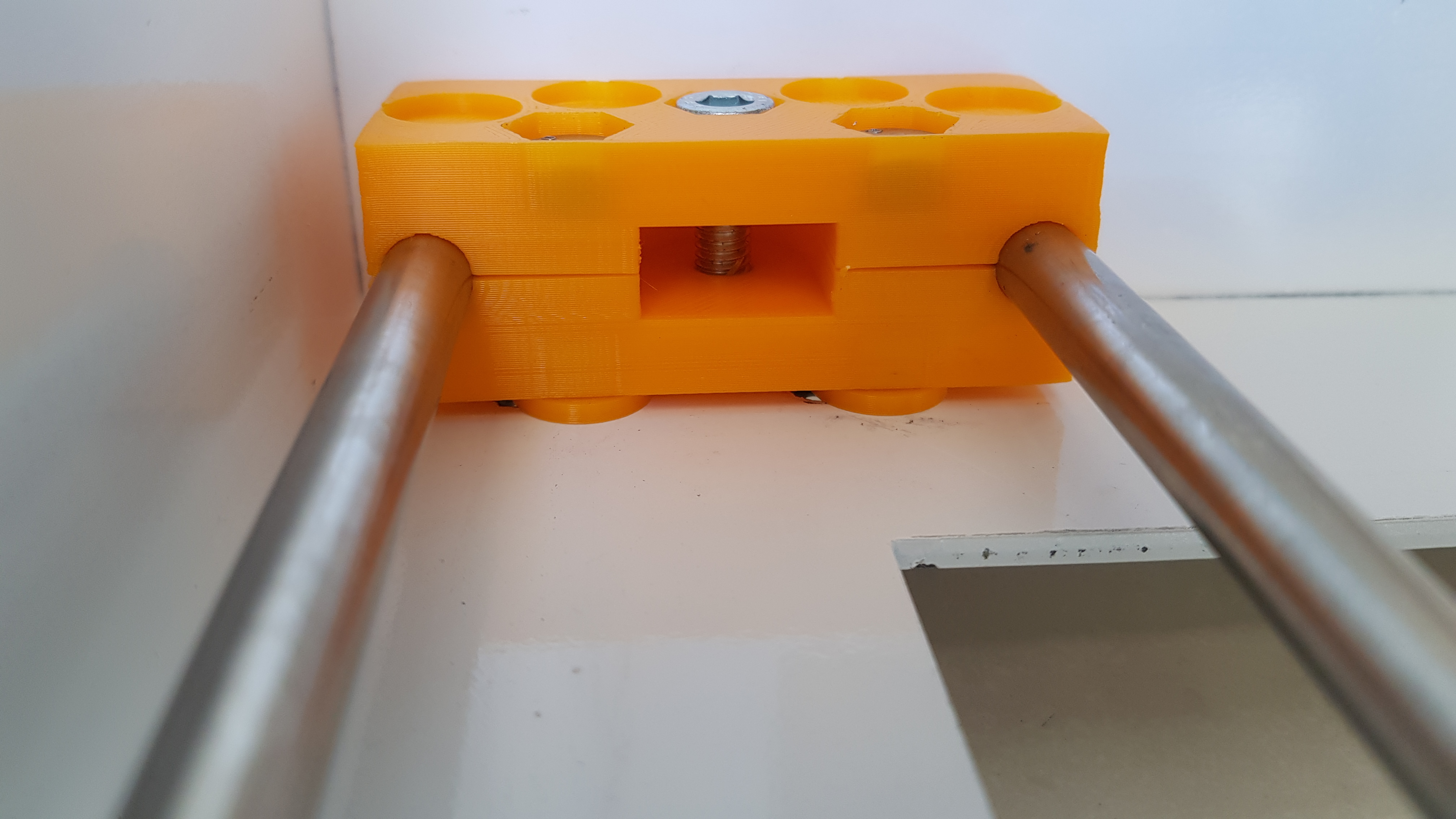
| 05:20, 6 January 2018 | Install x.jpg (file) |  |
2.56 MB | Access hole to tighten the bottom screw holding X-axis to the carriage. | 1 |
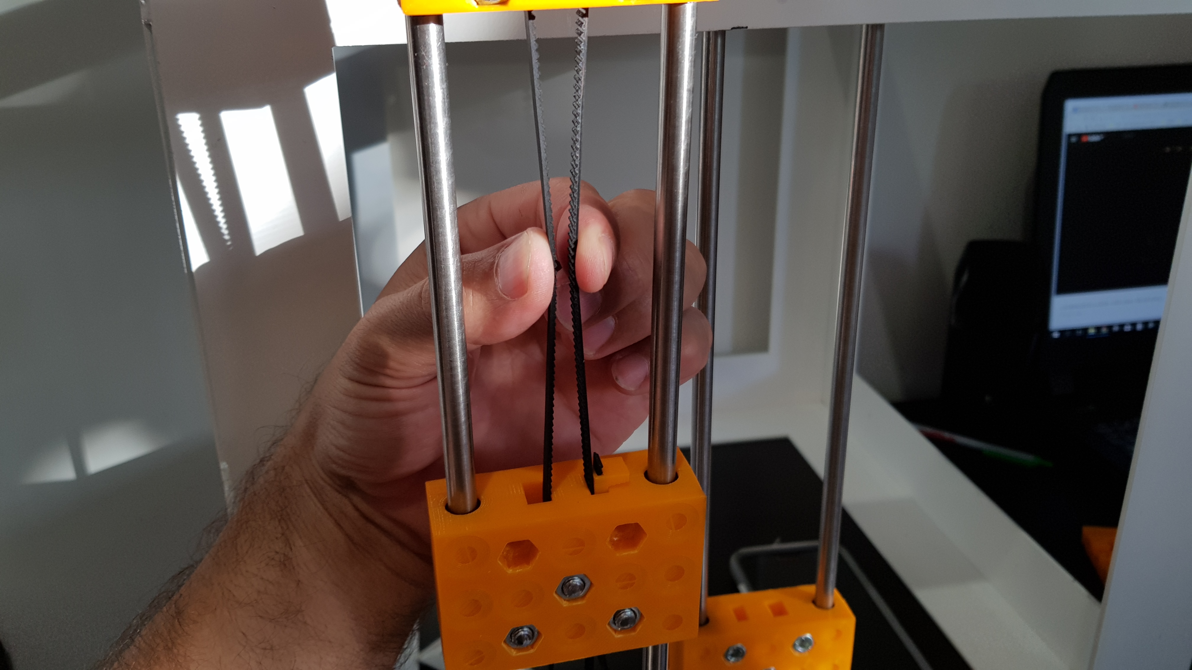
| 05:15, 6 January 2018 | Belt tension.jpg (file) |  |
2.15 MB | Tensioning belt by feel. | 1 |
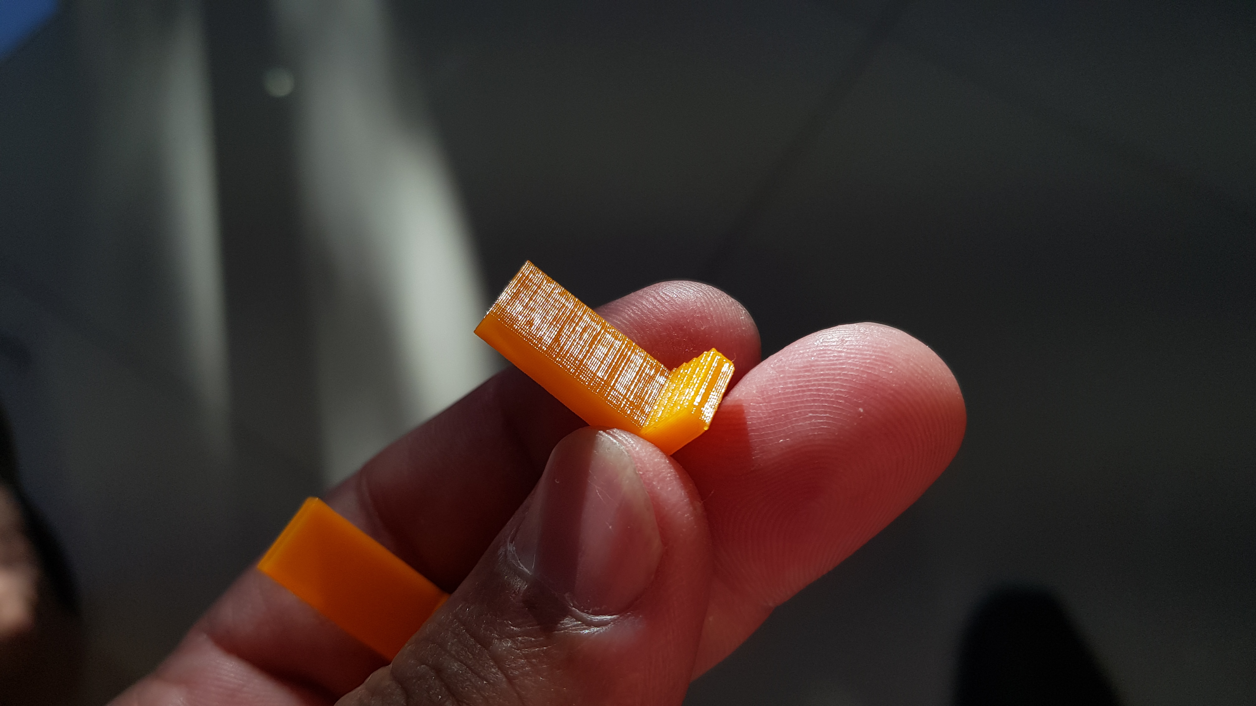
| 05:12, 6 January 2018 | One peg.jpg (file) |  |
2.51 MB | Belt-tightening peg | 1 |
| 05:10, 6 January 2018 | M6x30-2.jpg (file) |  |
2.49 MB | Trimmed off 2mm from M6x30mm SS screws. | 1 |
| 11:15, 3 January 2018 | All axes frame.jpg (file) |  |
15.74 MB | The disposition of all axes on the metal frame. | 1 |
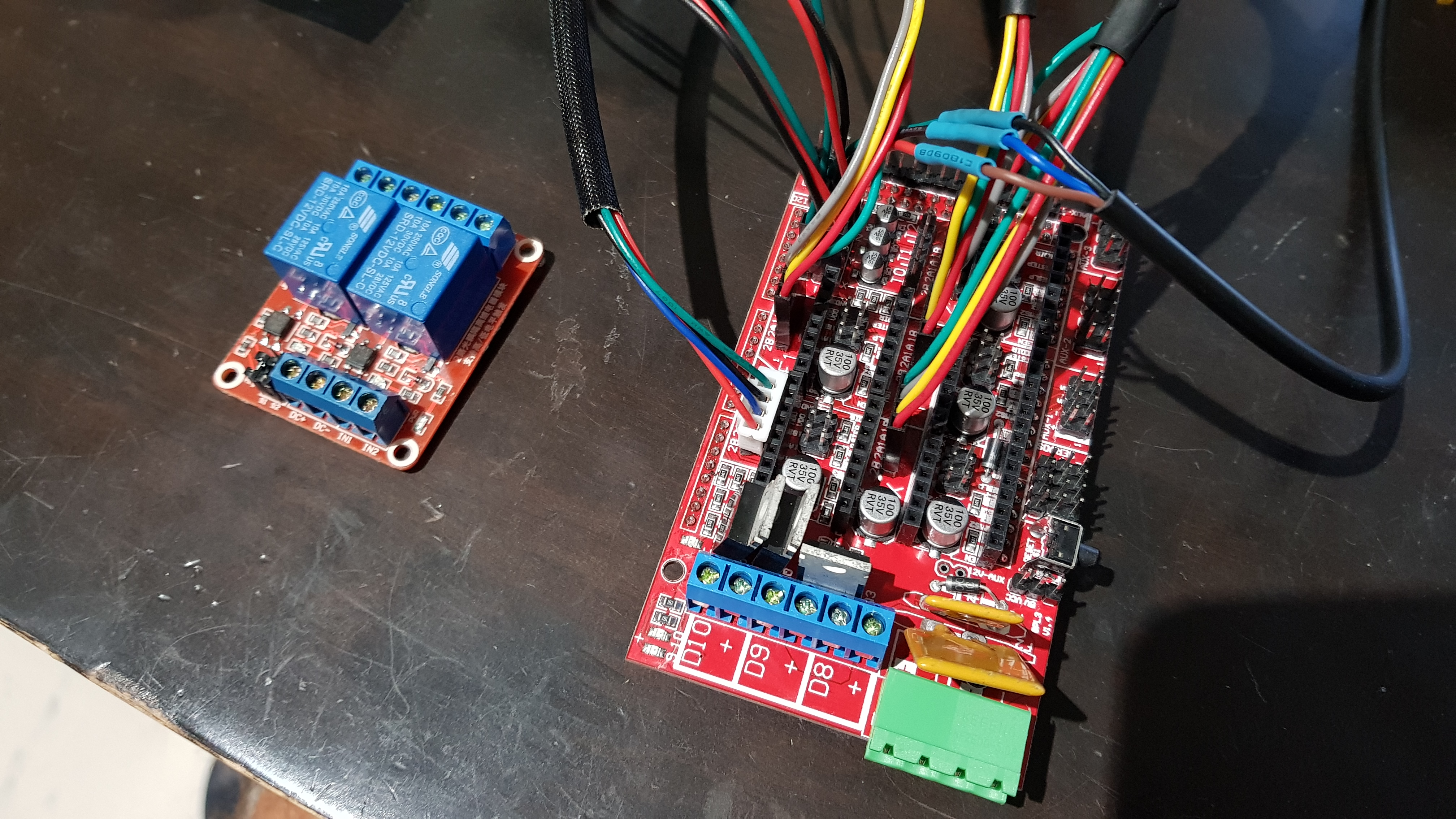
| 09:13, 1 January 2018 | Controller wiring.jpg (file) |  |
3.27 MB | Some of the wires to the controller. | 1 |
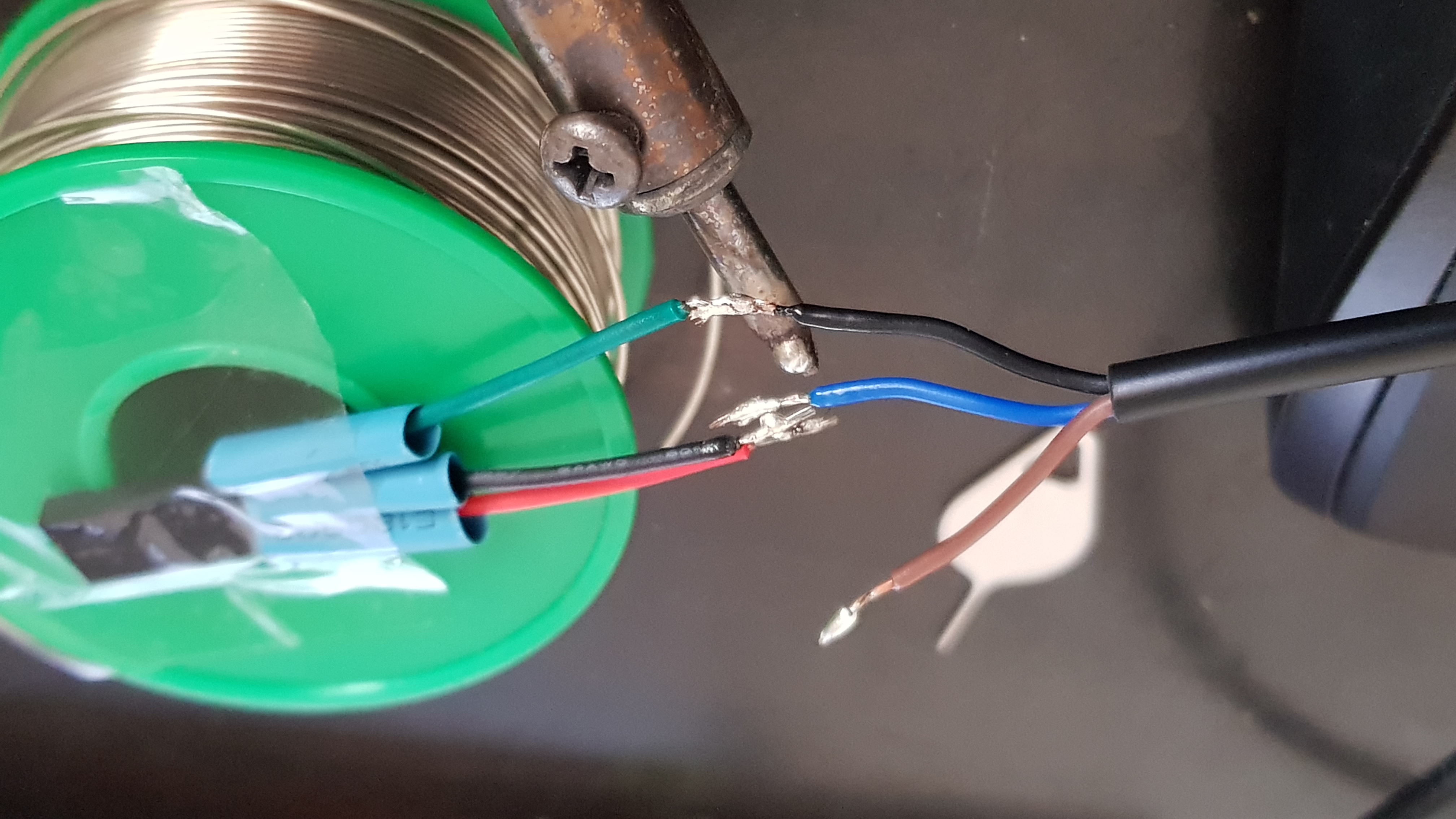
| 09:11, 1 January 2018 | Soldering inductive sensor.jpg (file) |  |
1.98 MB | Soldering inductive sensor's wires to Dupont end in the correct sequence. | 1 |
| 09:08, 1 January 2018 | Inducive sensor dupont.jpg (file) |  |
1.77 MB | Setting up wires to solder Dupont connector end to inductive sensor wiring. | 1 |
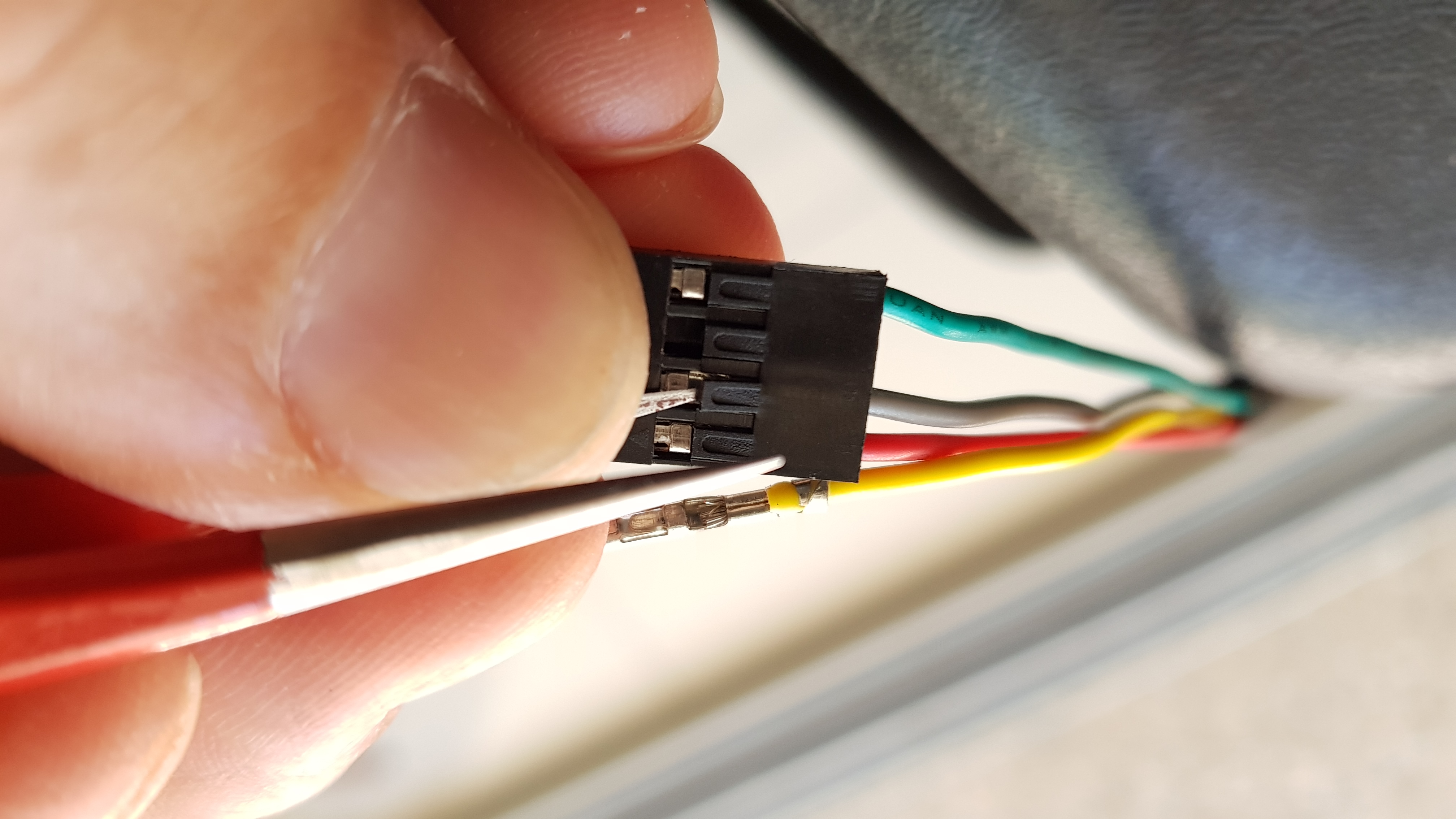
| 09:05, 1 January 2018 | Sequence dupont.jpg (file) |  |
1.77 MB | Changing wire sequence in Dupont connector. | 1 |
| 22:32, 30 December 2017 | X y y.jpg (file) |  |
3.04 MB | X and Y axes | 1 |
| 22:29, 30 December 2017 | Pulley alignment.jpg (file) |  |
2.22 MB | Correct alignment. | 1 |
| 22:26, 30 December 2017 | Motor pulley ok.jpg (file) |  |
2.01 MB | Correct placement of pulley. | 1 |
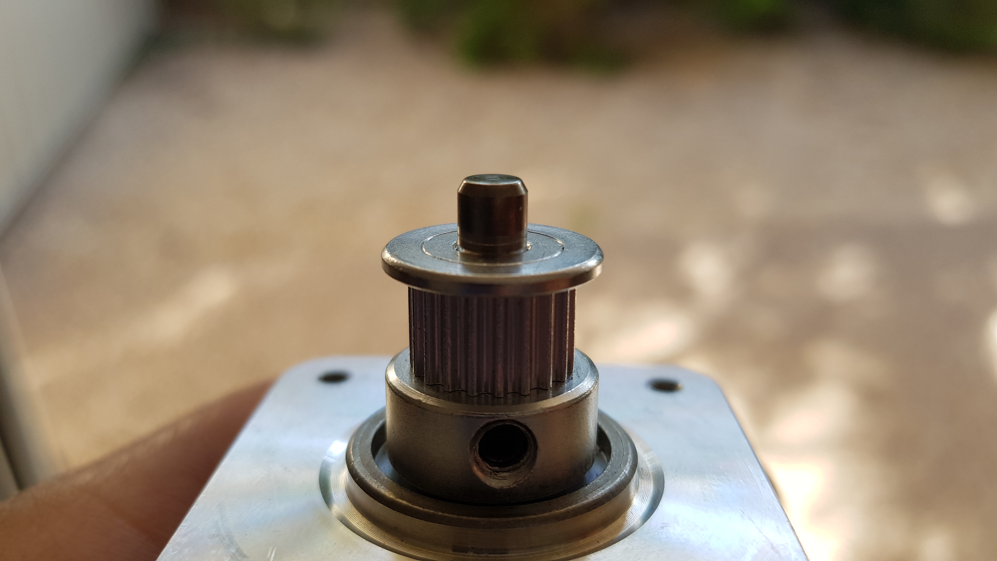
| 22:24, 30 December 2017 | Motor pulley ref.jpg (file) |  |
2.25 MB | Used a bearing as a reference to accurately place the pulleys on the motors. | 1 |
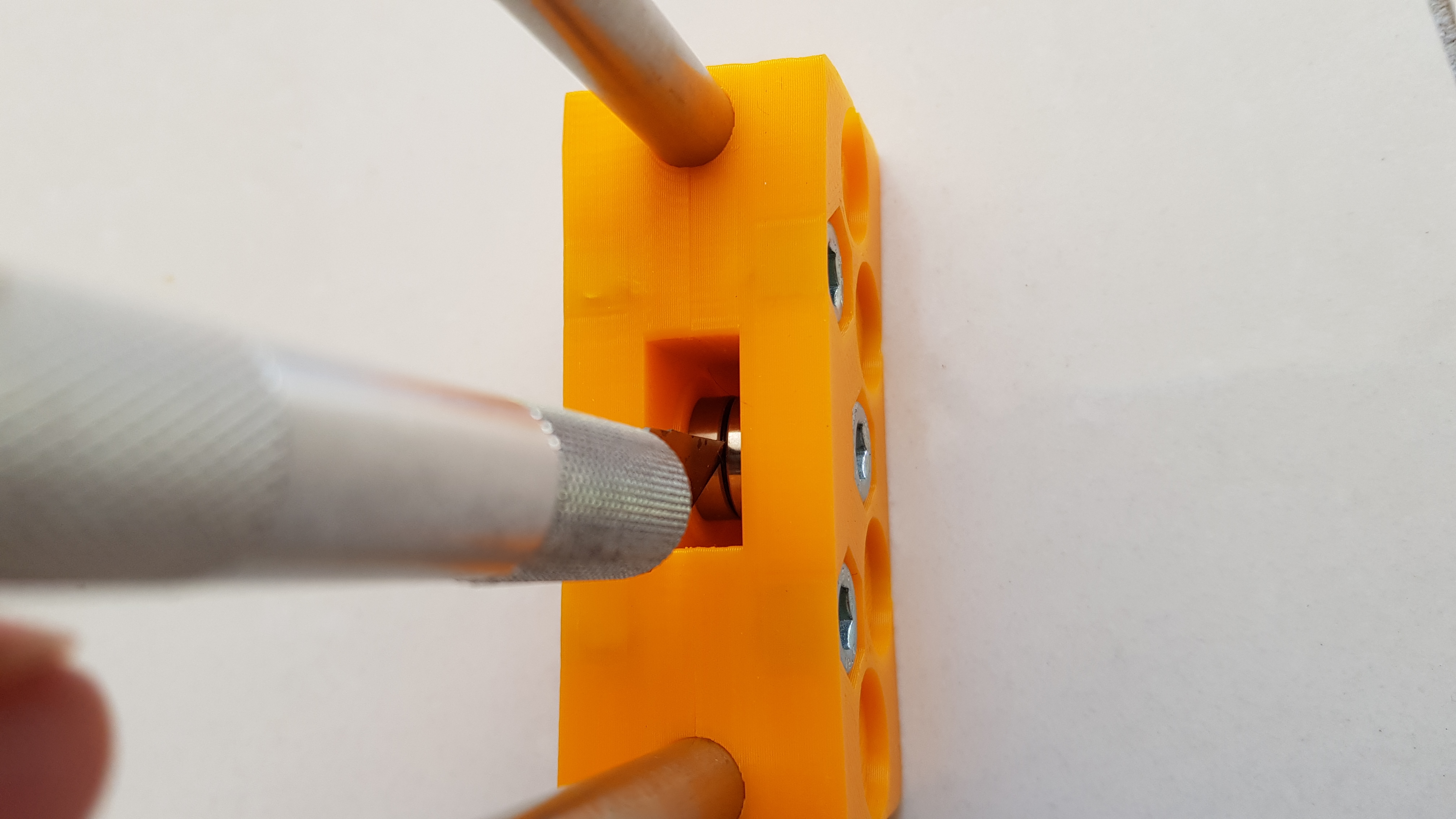
| 22:21, 30 December 2017 | Short idler tight.jpg (file) |  |
1.99 MB | A gap of around about 0.5mm must be seen between the two bearings | 1 |
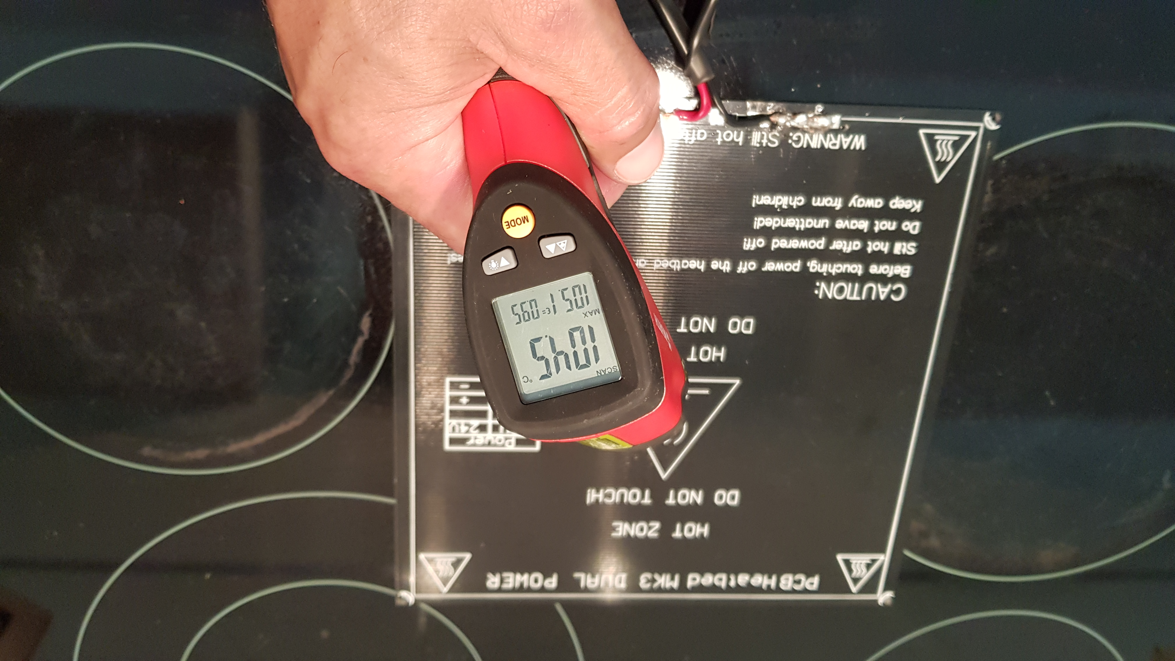
| 22:16, 30 December 2017 | HBP temp.jpg (file) |  |
3.11 MB | Maximum temperature reached by HBP without regulation. | 1 |
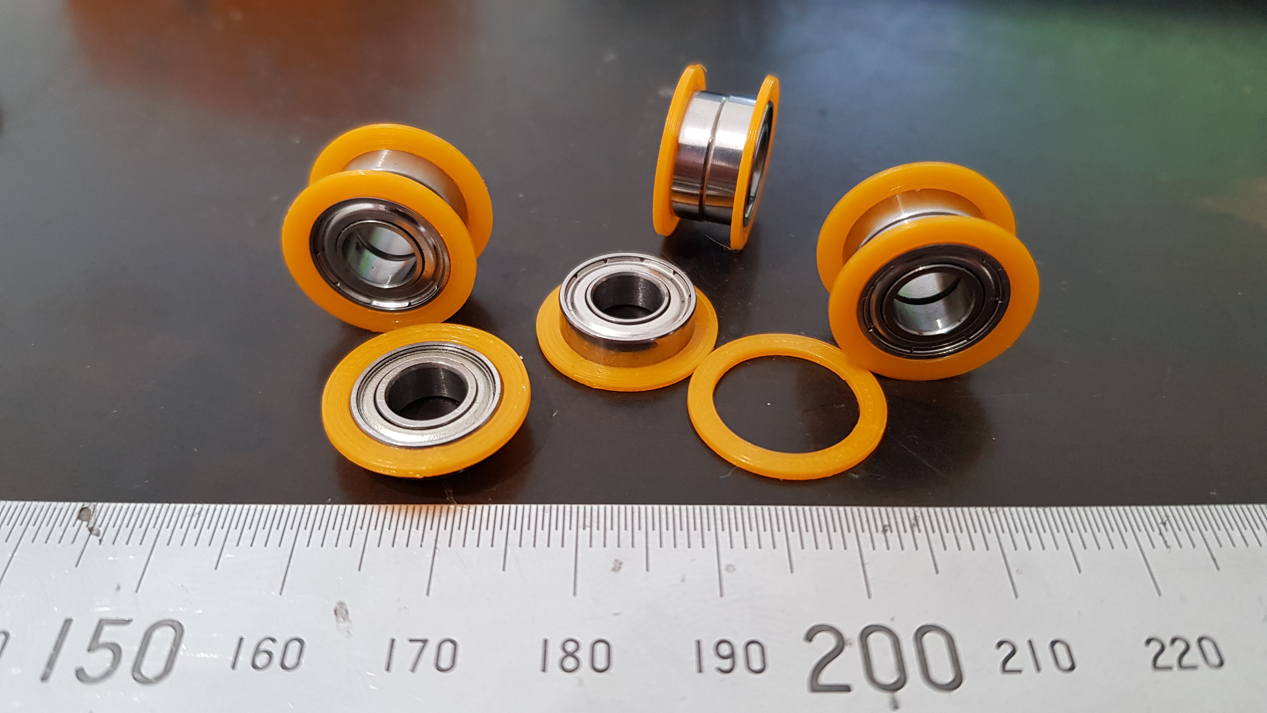
| 22:13, 30 December 2017 | Idler flanges on.jpg (file) |  |
2.82 MB | Printed flanges for idler bearings. | 1 |
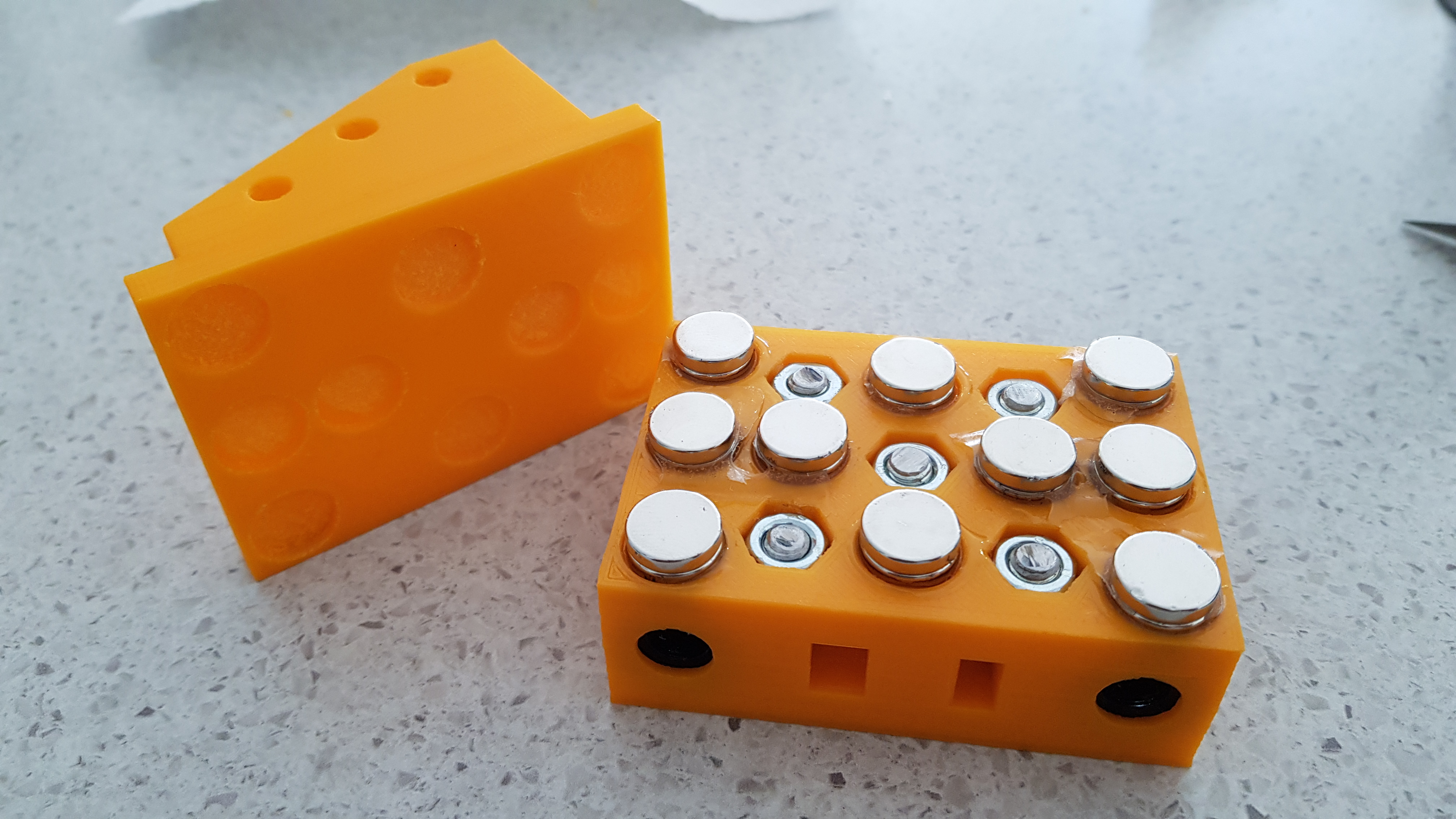
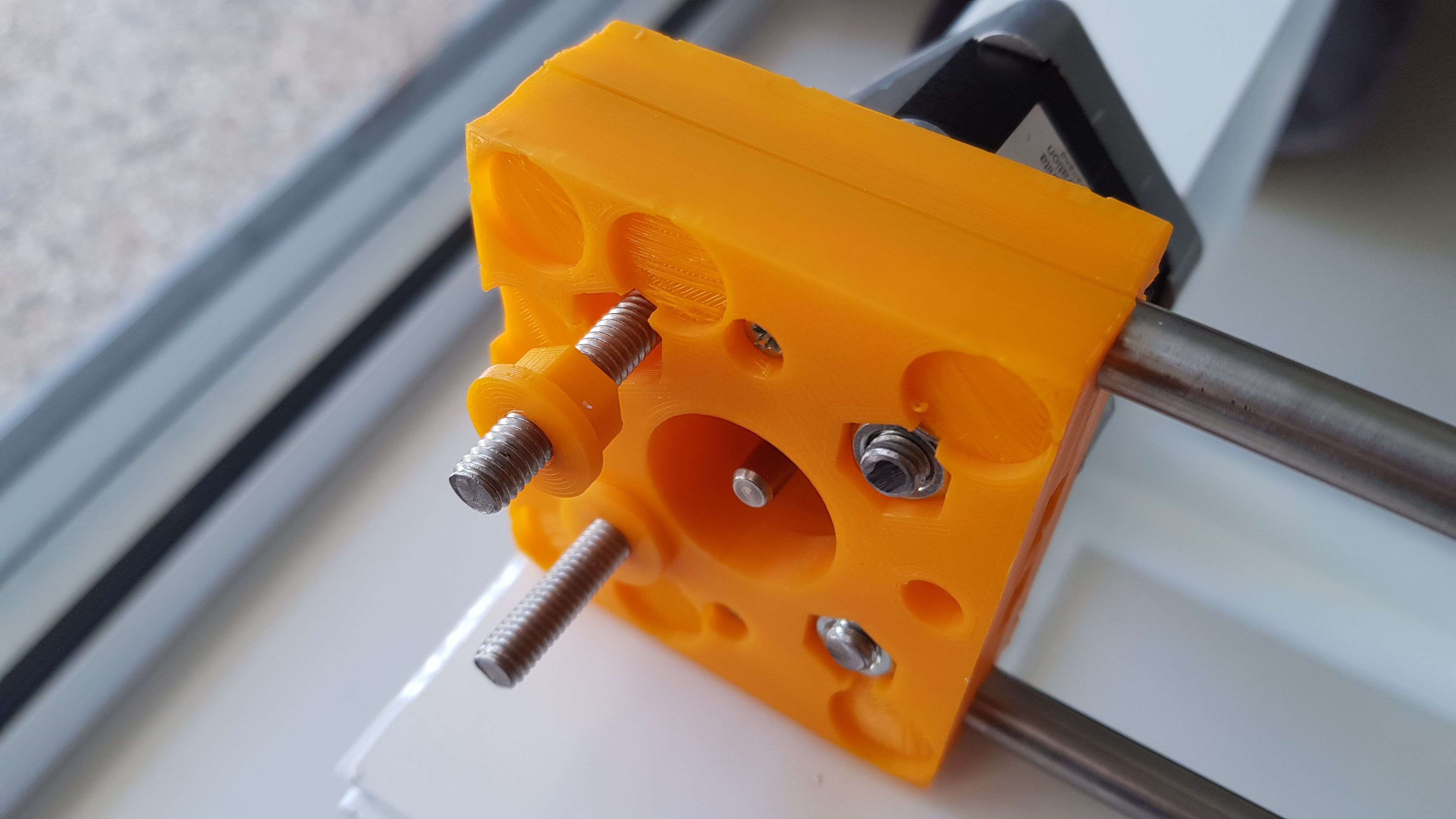
| 22:08, 30 December 2017 | Square interface carriage.jpg (file) |  |
2.75 MB | Proper alignment of parts after gluing the magnets. | 1 |
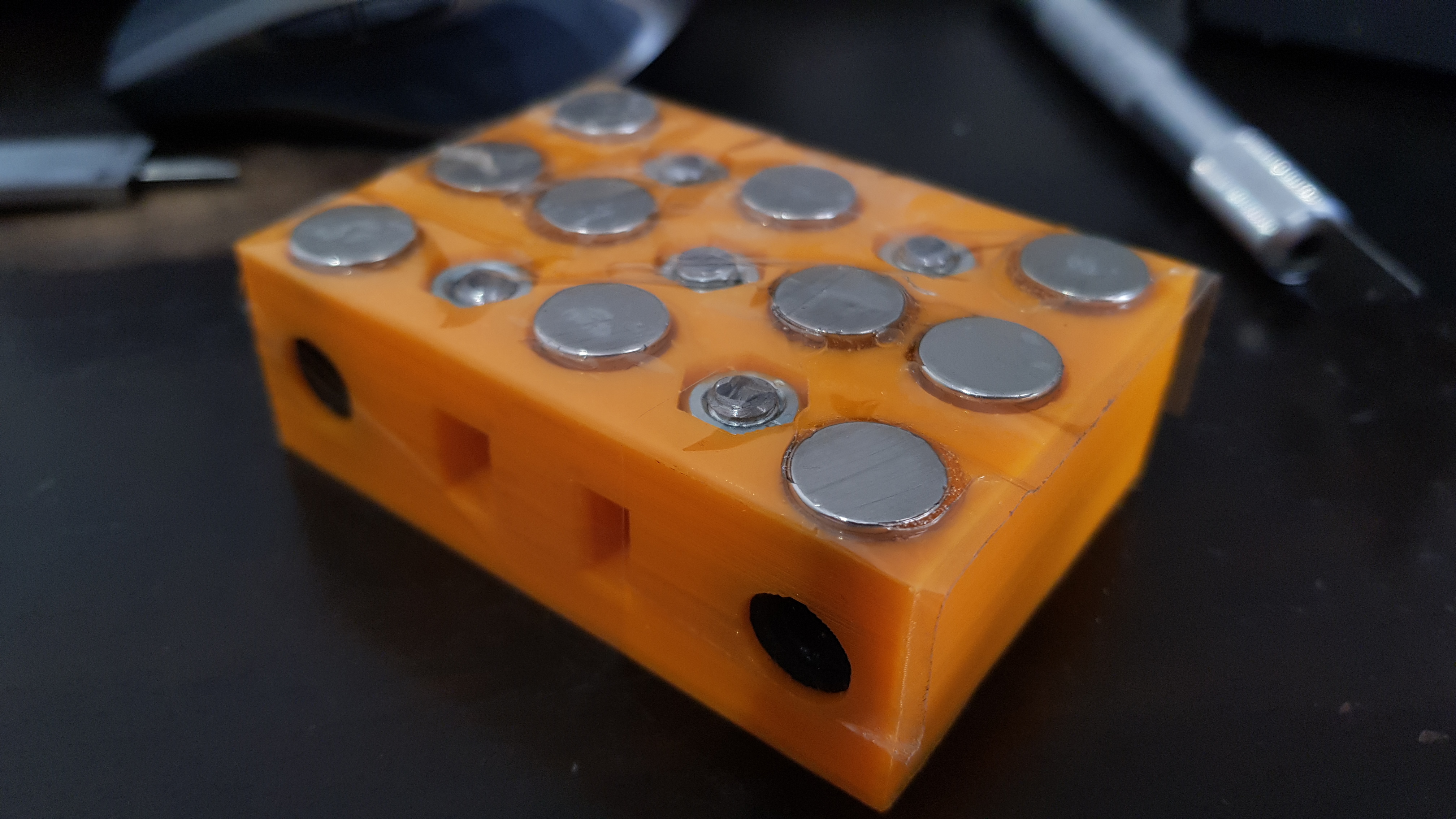
| 22:05, 30 December 2017 | Magnets epoxy.jpg (file) |  |
2.1 MB | Beads of epoxy on extruder interface. | 1 |
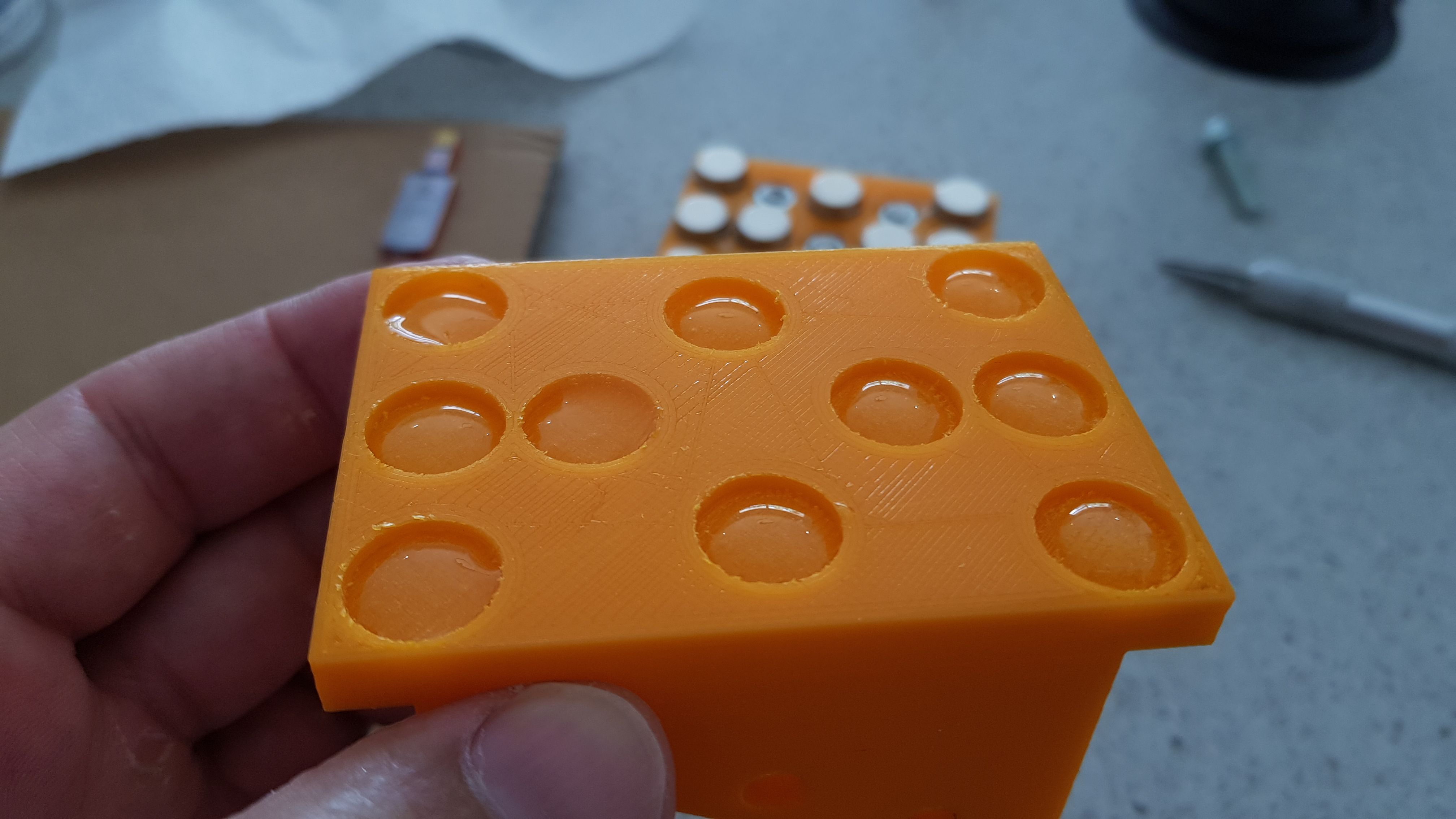
| 22:02, 30 December 2017 | Magnets extruder interface.jpg (file) |  |
2.54 MB | Sticking the magnets of the extruder interface to the carriage assembly before gluing. | 1 |
| 21:58, 30 December 2017 | Magnets taped.jpg (file) |  |
2.64 MB | Magnets being held down by tape while gluing. | 1 |
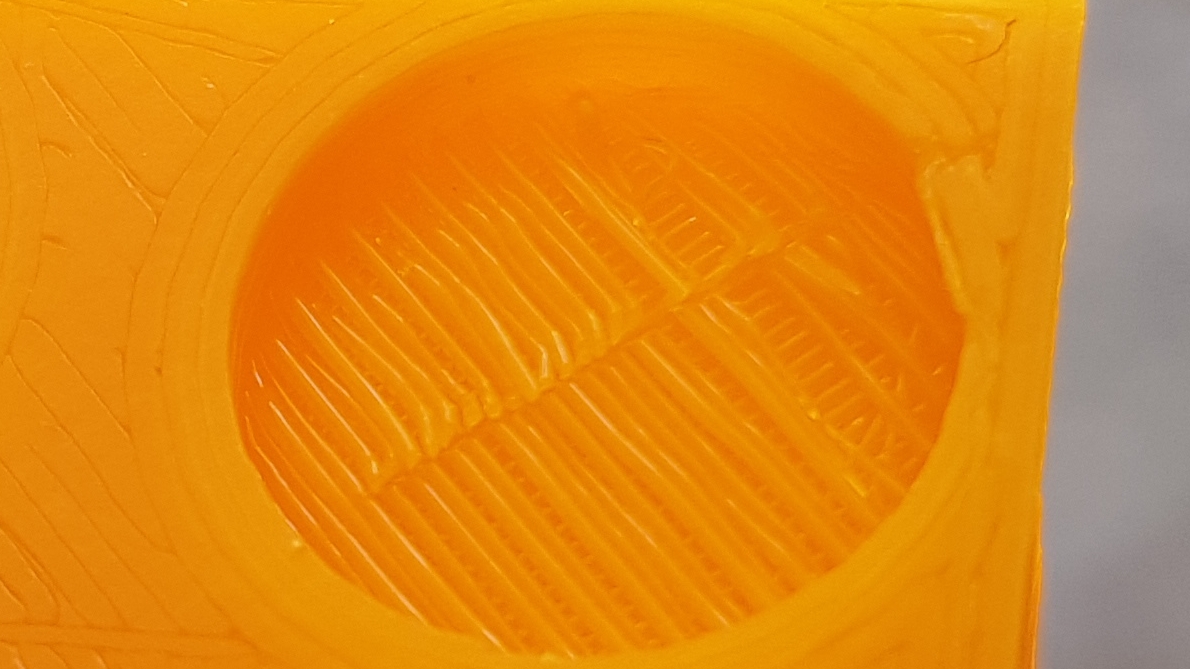
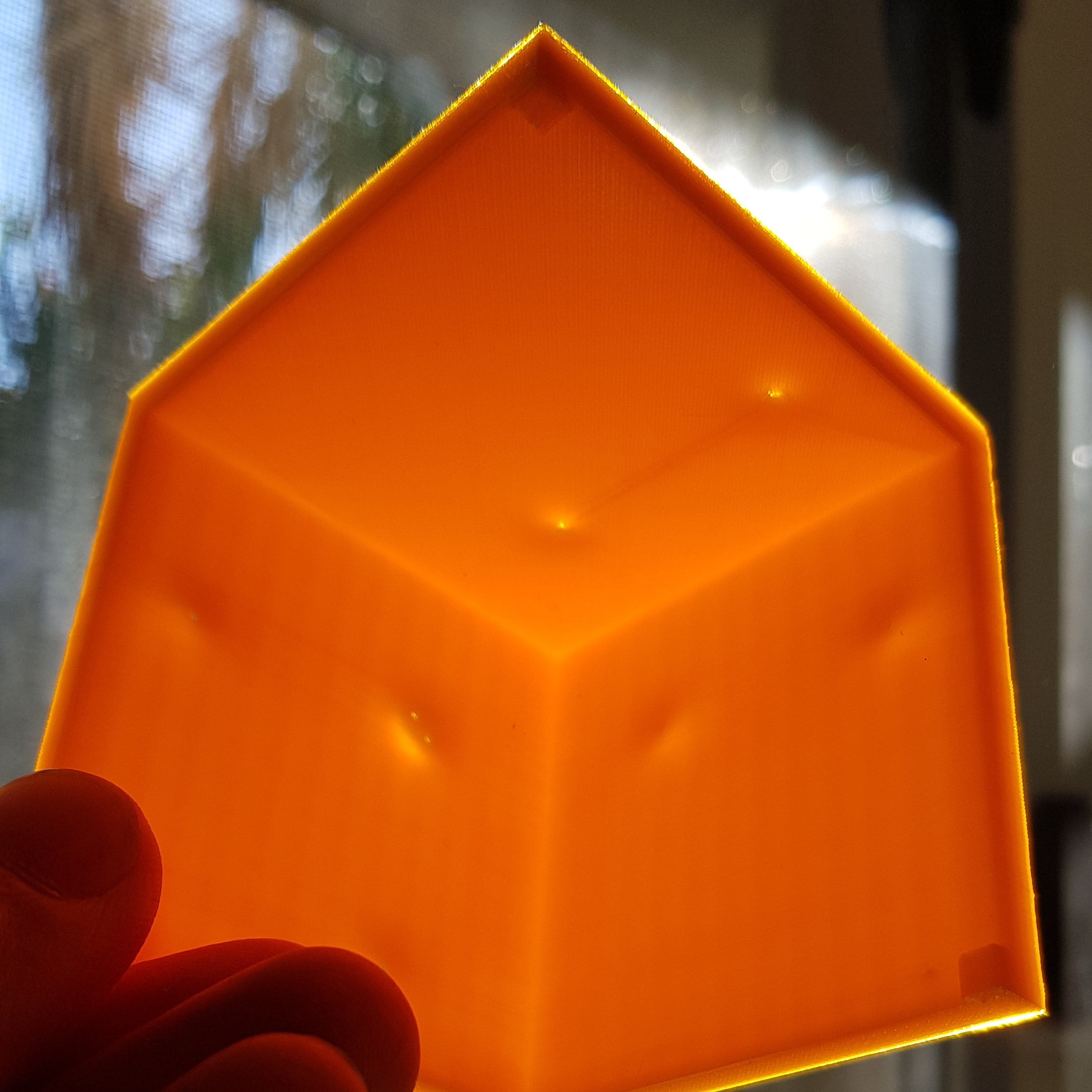
| 21:54, 30 December 2017 | Bridging scraped.jpg (file) |  |
2.36 MB | Scraping of the loose layer in a bridged gap of the print. | 1 |
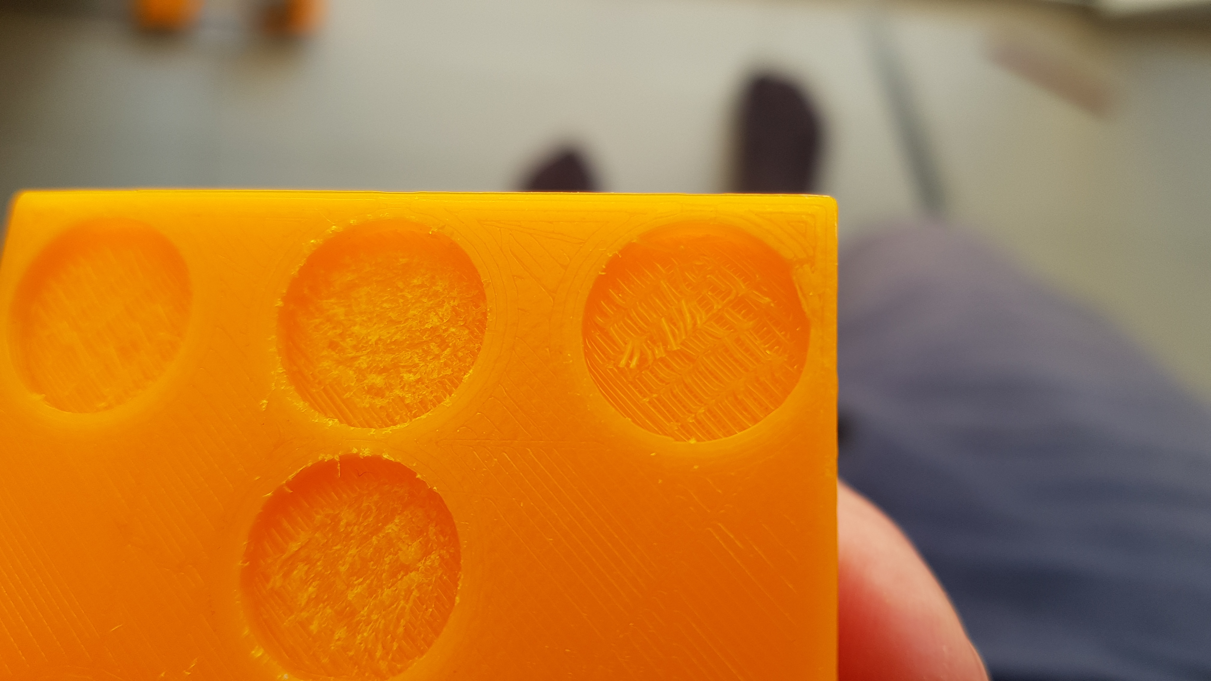
| 21:50, 30 December 2017 | Bridging filaments.jpg (file) |  |
410 KB | Lack of adhesion between the first layer the bottom of a magnet socket and the following layer due to the printer having to bridge the gap. | 1 |
| 05:27, 27 December 2017 | Aus spacer idler.jpg (file) | 2.07 MB | Detail of the spacers on the idler side. | 1 | |
| 05:26, 27 December 2017 | Aus spacer motor.jpg (file) | 2.06 MB | Detail of the spacers on the motor side. | 1 | |
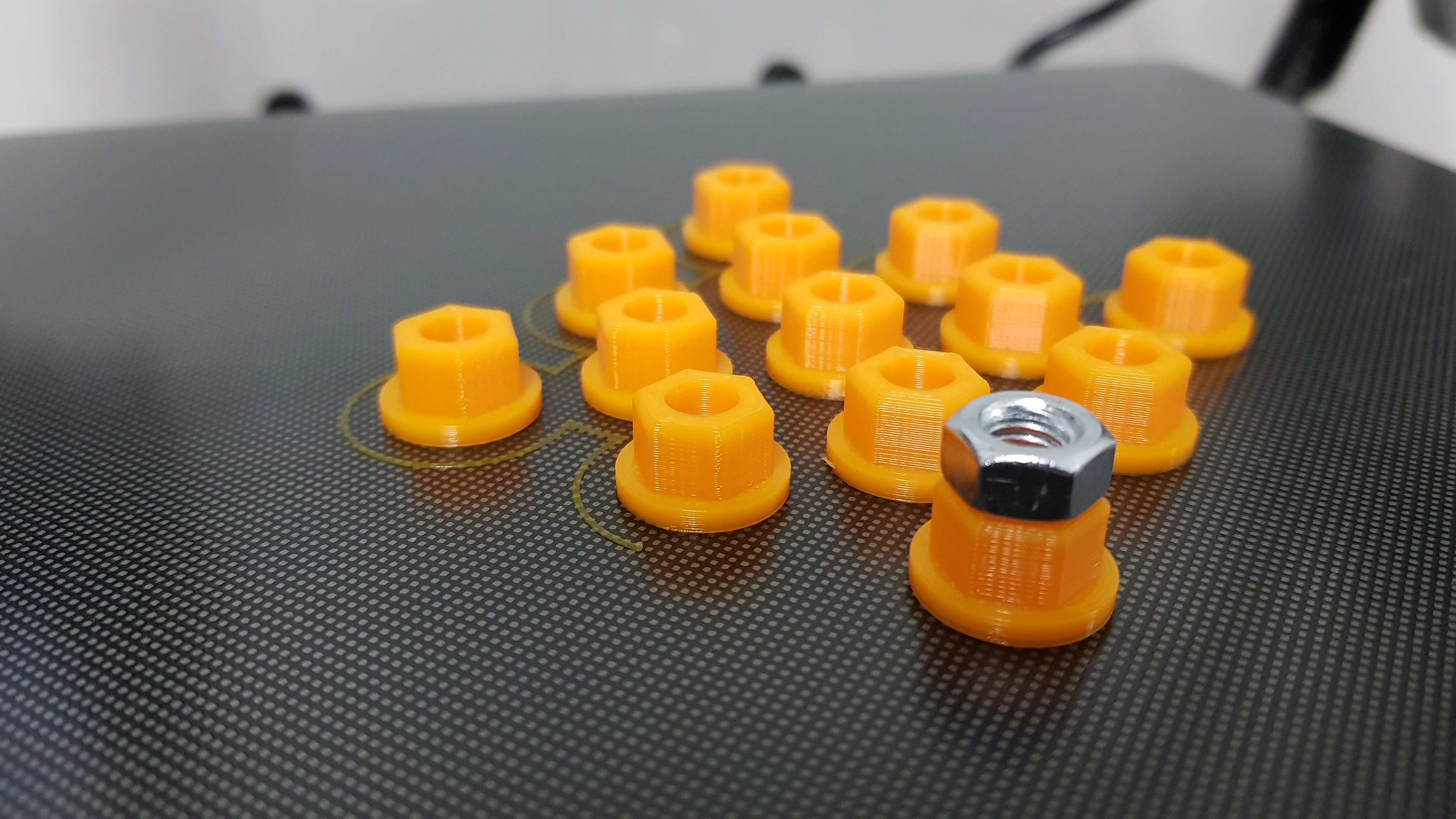
| 05:23, 27 December 2017 | Aus spacers.jpg (file) | 2.89 MB | Spacers to mount axes using the bolts that squeeze the end sandwiches (motor and idler) together. | 1 | |
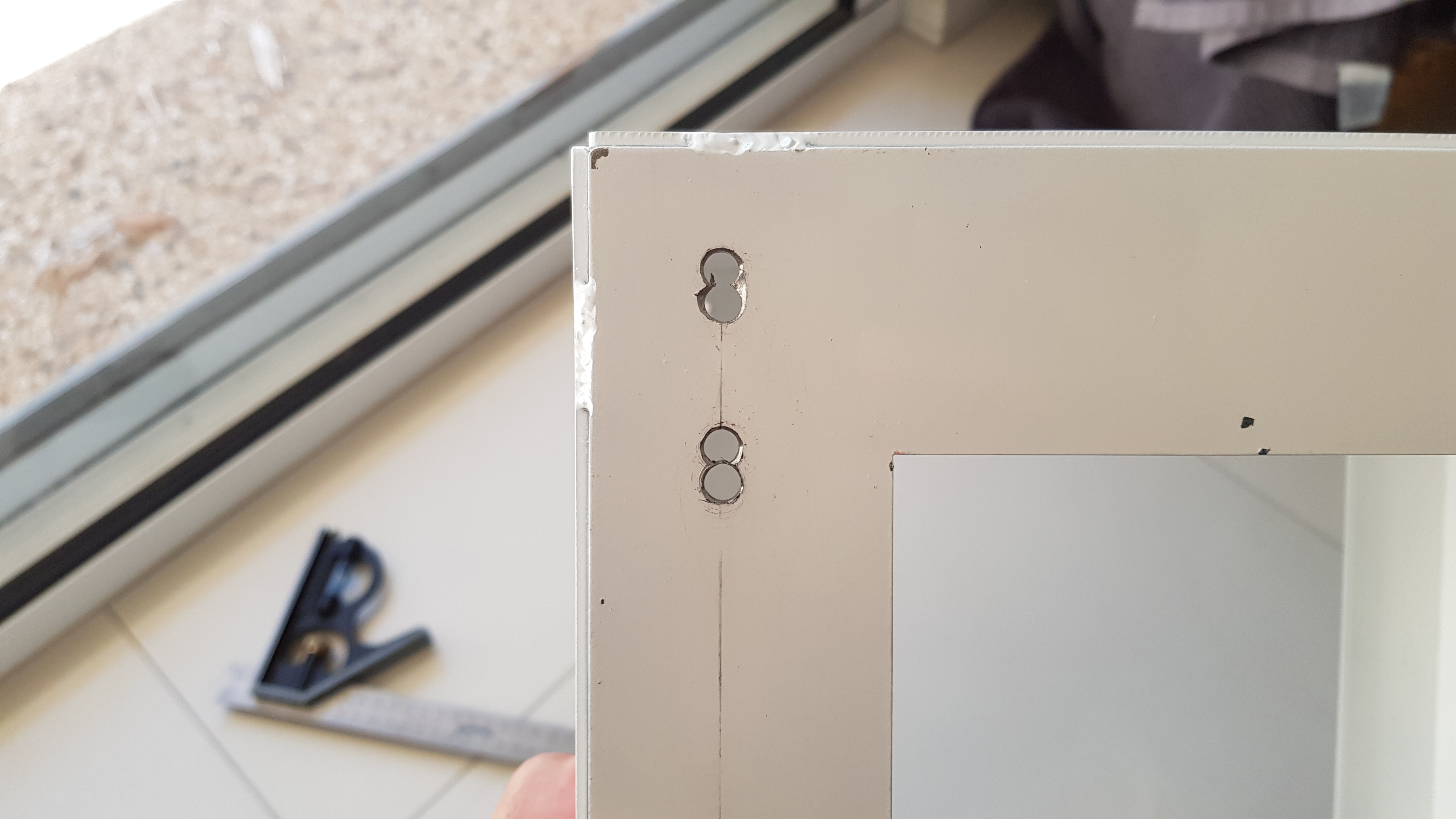
| 05:21, 27 December 2017 | Aus holes misplaced.jpg (file) |  |
2.1 MB | Redrilled holes. Displaced 6mm to be able to drill next to the first set. | 1 |
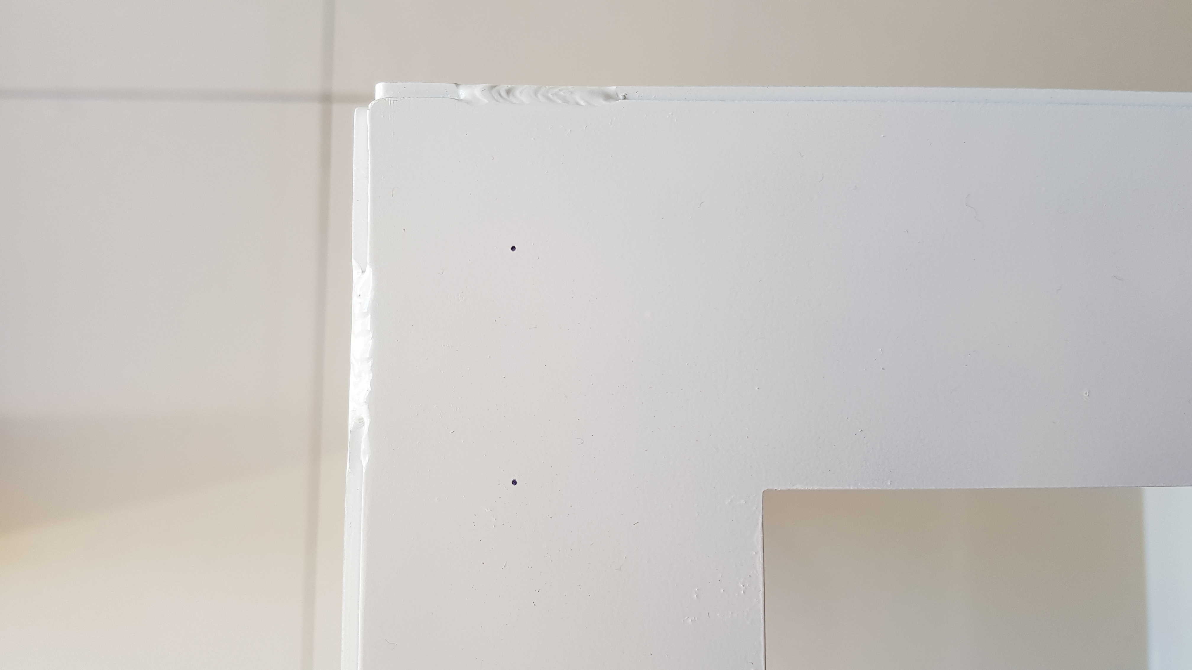
| 05:18, 27 December 2017 | Aus hole marks.jpg (file) |  |
1.79 MB | Markings placed with template tool. D3D Australia | 1 |
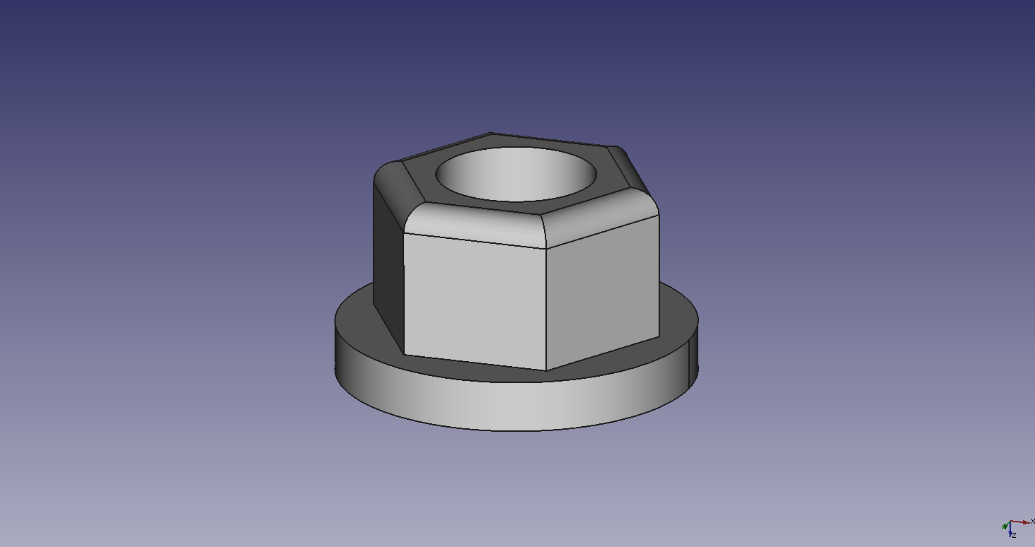
| 11:25, 26 December 2017 | D3DAustralia Axes Spacer.png (file) | 20 KB | Spacers that allow for a 2mm separation between D3D frame and all axes assemblies when affixed with bolts. | 1 | |
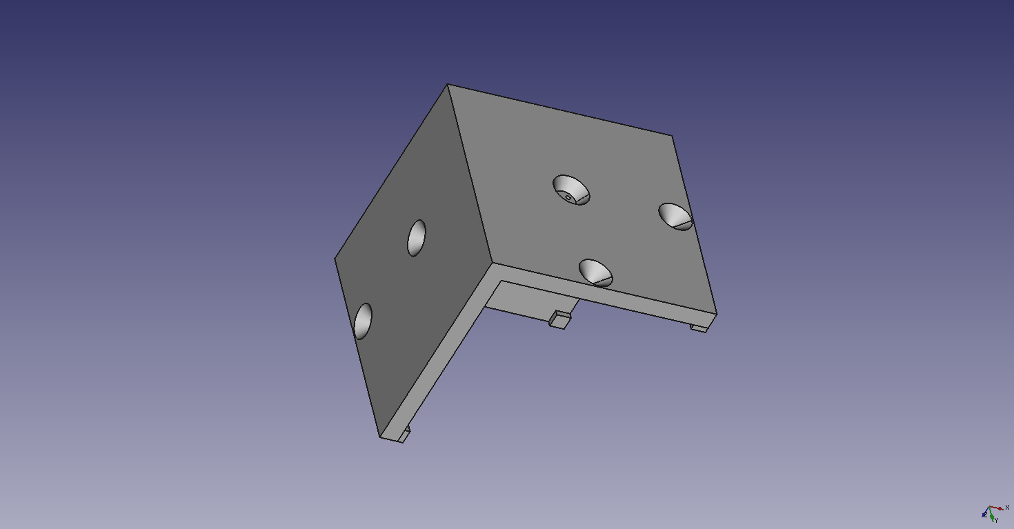
| 11:18, 26 December 2017 | D3DAustralia Holes Template.png (file) |  |
21 KB | Template to accurately place guide marks for the holes where the Y axes mount to the frame of the printer. | 1 |
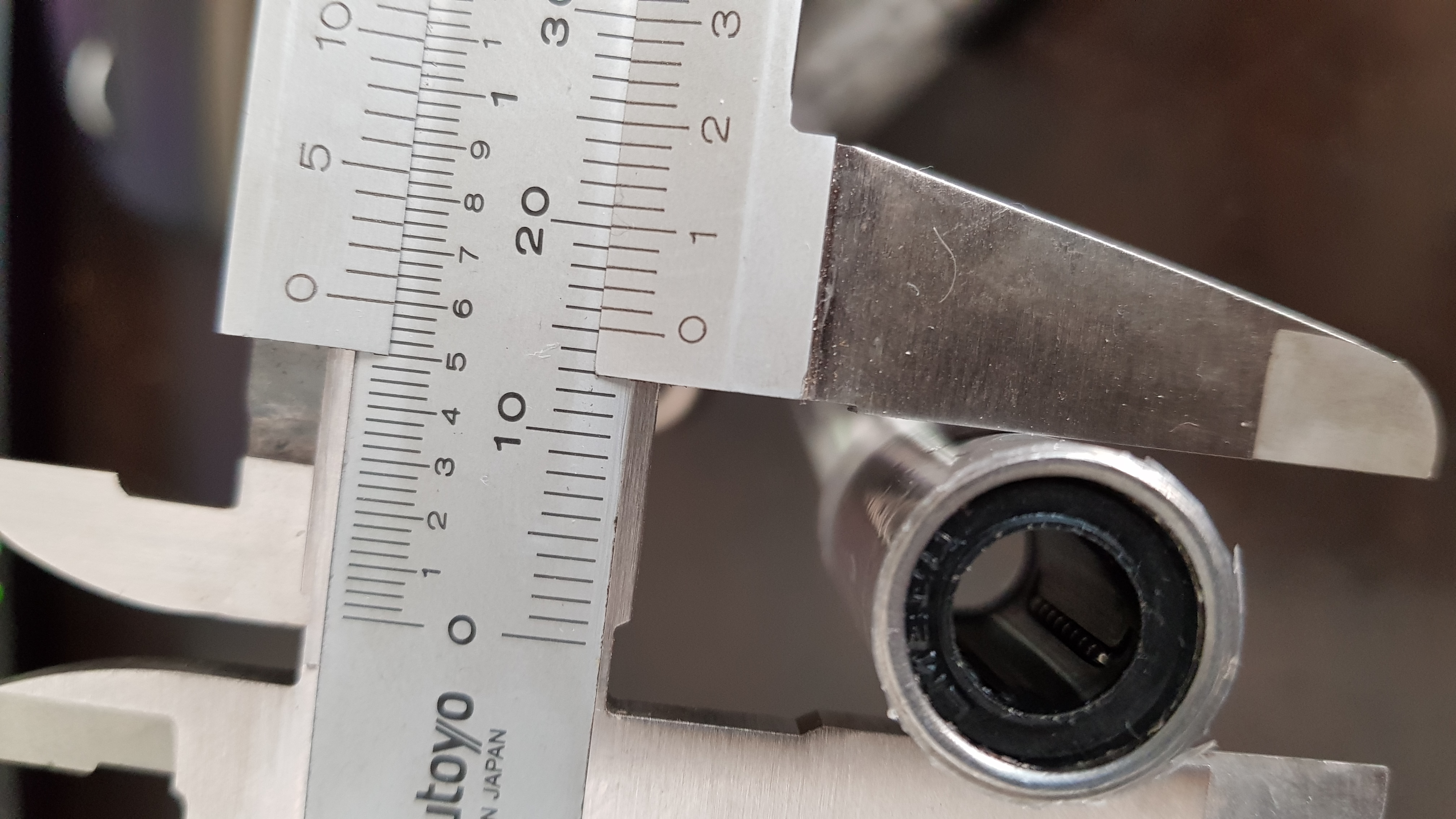
| 12:16, 23 December 2017 | Linear bearing tape00.jpg (file) |  |
2.5 MB | Measuring increased diameter on a linear bearing. | 1 |
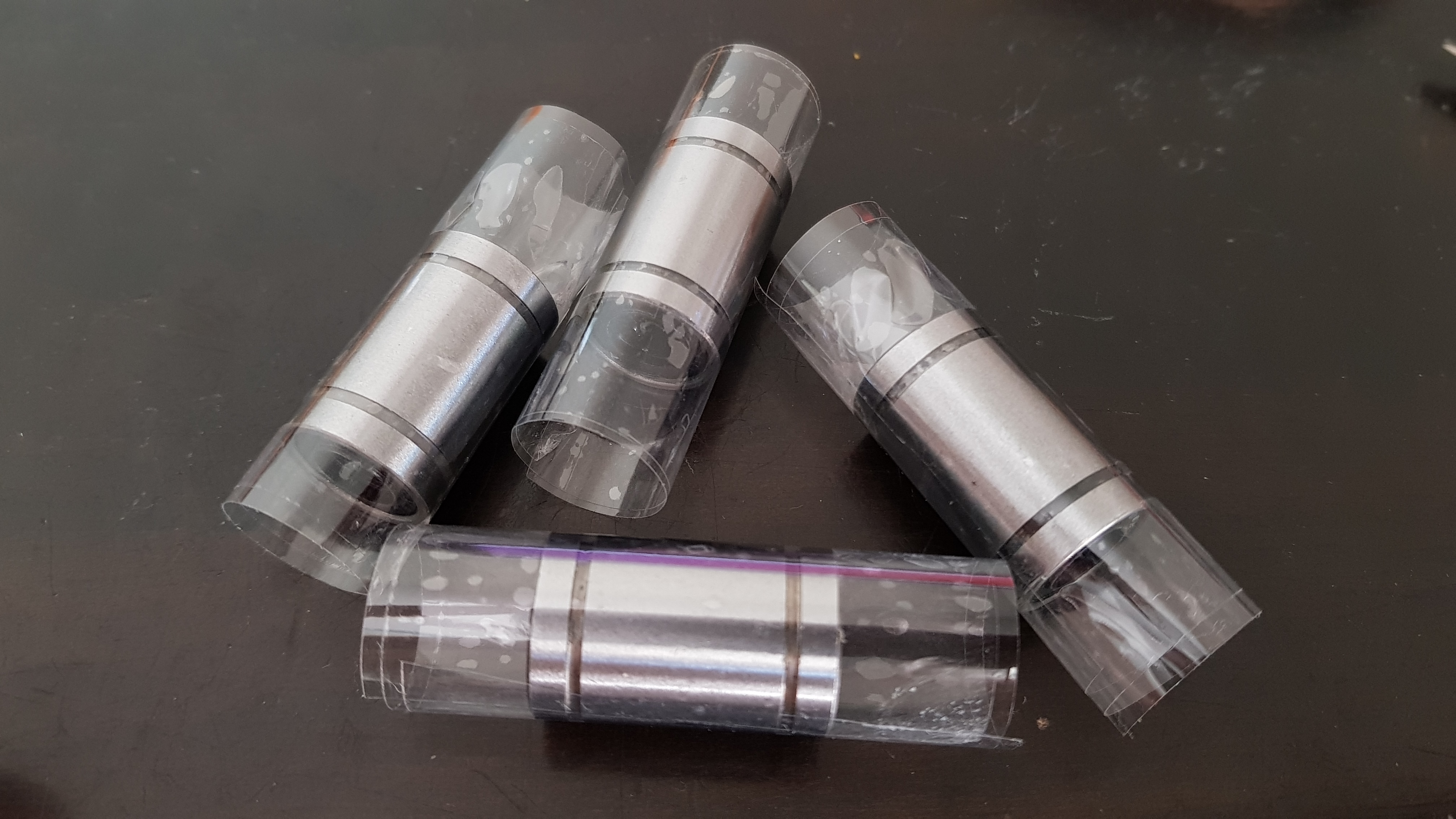
| 12:14, 23 December 2017 | Linear bearing tape.jpg (file) |  |
2.48 MB | Linear bearings with increased diameter. | 1 |
| 12:00, 23 December 2017 | Holes template01.jpg (file) |  |
672 KB | Template to place holes on the D3D frame's corners. | 1 |
| 11:59, 23 December 2017 | Holes template02.jpg (file) |  |
506 KB | Template to place holes on the D3D frame's corners. | 1 |