The Liberator Assembly
Jump to navigation
Jump to search
After unpacking the crate as in The_Liberator_Packing_List, you are ready to assemble the machine. The assembly procedure is the reverse temporal order of the disassembly video from the blog:
Assembly begins by locating a flat spot on the ground, preferably in a covered space in case of foul weather.
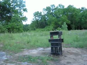
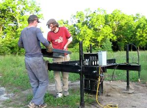
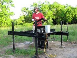
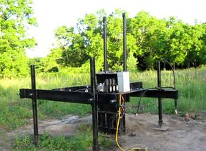
- Place the main frame flat on the ground as shown in figure Step 1. The machine front is defined as the orientation of the frame in which the main cylinder senor is on your right hand side when facing the machine frame. Right and left sides are defined accordingly.
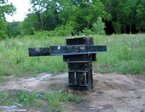
- Attach the primary arms using the bolts provided. The primary arms are those arms without the leg holders. The right hand arm, which is the one with the greater number of holes, should be on the right side shown in Step 2. Do not tighten the bolts at this point, until the secondary arms are fit onto the primary arms.
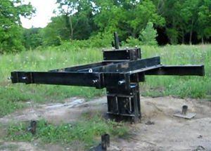
- Attach the secondary arms using the bolts provided. The front arm shown in Step 3 is the one with the secondary cylinder attachment eye, and the 4" side of this arm is below the 6" side. The rear arm has the 6" side oriented below the 4" side.In this step, attaching the front arms will make the machine tilt forward unless it is otherwise supported by holding, jacking up, or inserting the legs, as in the next step. Tighten down the secondary arm bolts, and once these are tightened, the primary arm connection to the frame may be tightened up.
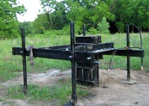
- Attach the legs and feet by placing the legs in the sleeves and tightening the bolts. Attach the legs in the outer leg positions, not in the inner position as shown in Step 4.
- Attach the solenoid valve with 2 bolts (3/8") into the corresponding set of holes. There should be a hole in the frame below the pressure relief on the valve. There is only one way that the solenoid valve can be attached, so the corresponding holes should be apparent.
- Attach the controller box using one 1/2" bolt to the right of the solenoid valve.
- Install the roller guides. The guides can go in only one way - the guide body should be over the guide roller adjusters. Do not overtighen the bolt that connects the roller guides to the u-channel. The roller guides should be able to pivot slightly around this bolt
- Install the soil-loading drawer into the frame, as in Step 5. Adjust the roller guide adjustment bolts (4 of them) such that the drawer can roll freely on the guides, with its bottom not touching the frame throughout its motion. The top of the drawer should not touch the frame either. Adjust the roller guide ajustment bolt such that the top surface of the drawer barely touches the frame, while the space on the bottom may be larger.
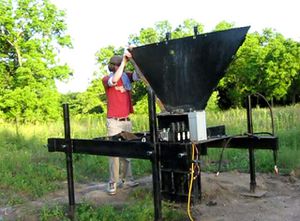
- Install the hopper mounting plate and tighten the 4 bolts as in Step 6. The wider edge of the plate should face forward.
- Install the rear hopper supports, as in Step 7. Wait for the rear hopper sheet to be installed to determine the vertical adjustment of the rear hopper supports.
- Install the back piece of the hopper. This is the largest sheet. See Step 8.
