Motor selection
THIS INSTRUCTION IS IN PROGRESS AND NOT READY FOR USE.
The selection of motor includes the following steps (which are described in further detail on this page):
Step 1) Select the motor type
Step 1.1) Identify application and desired motor attributes
Use the table below to select one of four motor types that correspond to your application and the desired motor attributes.
| Attribute | Stepper motors | Servo motors | Brushed DC motors | Brushless DC motors |
|---|---|---|---|---|
| Area of use | Low speed and low acceleration | High speed and high acceleration. The trade-off is higher cost and complexity. | Continuous rotation at high RPMs and constant torque across the motor’s speed range. | Continuous rotation at high RPMs and constant torque across the motor’s speed range. |
| Application examples |
• floppy disk drives • flatbed scanners • computer printers • plotters • slot machines • image scanners • compact disc drives • intelligent lighting • camera lenses • CNC machines and 3D printers • Textile machines • Printing presses • Medical imaging machinery • Small robotics • Welding equipment |
• Automated manufacturing • Robotics • CNC machinery • Telescopes • Elevators • Conveyor Belts • Camera Auto Focus • Solar Tracking System • Metal Cutting & Metal Forming Machines • Antenna Positioning • Printing Presses/Printers • Automatic Door Openers |
• Home appliances • toys • electrical propulsion • cranes • paper machines • steel rolling mills |
• Drones • Electric cars • Washing machines • Air Conditioners • Cordless tools • Computer • Fans • Disk drives |
| Accuracy | High | High (achieved by adding encoder to the system.) | None | Varies |
| Torque at low speeds | High | High | - | - |
| Torque at high speeds | Low (can lose up to 80% torque at high speeds) | High | - | - |
| Cost efficiency | High | Lower (uses rare-earth magnets, may need encoder or gearbox.) | High | Lower |
| Lifespan | Long life | Shorter | Shorter | - |
| Size | Compact | High output power relative to size and weight. | Compact | - |
| Load capacity | Low (might skip steps at high loads.) | High | - | - |
| Efficiency | Low (constantly draw maximum current independent of load.) | High (80–90% efficiency.) | High | - |
| Ease of use | • Easily controlled (can be controlled with micro controllers such as the ATmega chips that are readily available on Arduino development boards.) Can stall or lose position without a control loop. | • Higher maintenance if gearbox and encoder is included.
• Limited range of motion; positional rotation servos are limited to 180 degrees of motion. • Works in AC or DC drive. |
• Torque to Speed Ratio can be altered (exclusive to brushed motors.)
• High maintenance requirements due to easily worn out as a result of continuous moving contact. |
• Some brushless motors are difficult to control and require a specialized regulator.
• Low maintenance. |
Step 1.2) Confirm Load characteristic
Look at the Load characteristics type in the table below and identify which Load characteristic corresponds to your application. Then confirm that the motor type you selected from the table above corresponds to the identified Duty cycle.
| Load characteristic | Application examples |
|---|---|
| Torque that is constant | conveyors, extruders, bulk material conveyors, extruders, positive displacement pumps |
| Torque that changes abruptly | elevators, compactors, punch presses, saws, and batch conveyors |
| Torque that change gradually over time | centrifugal pumps, fans, blowers, compressors with unloaders |
Step 1.3) Confirm Duty cycle type
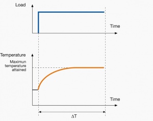
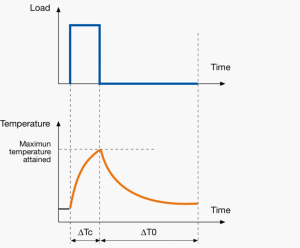
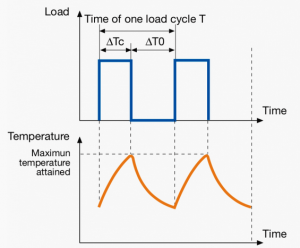
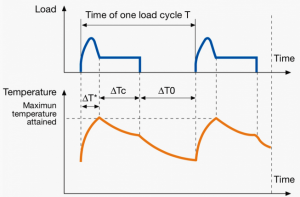
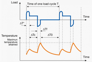
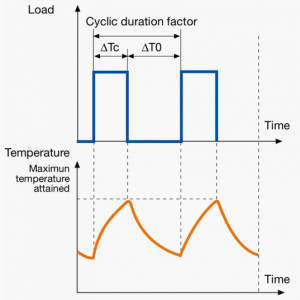
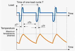
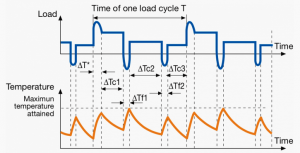
Look at the Duty cycle types in the table below and identify which Duty cycle corresponds to your application. Then confirm that the motor type you selected from the table above corresponds to the identified Duty cycle.
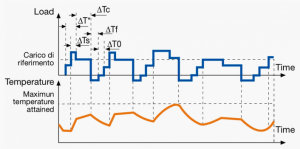
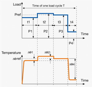
A duty cycle type specifies the sequence and time duration the motor operation including Starting, Running with no load, Running with a full load, Electric braking, and Rest. How the operations affect motor temperature determines whether increased cooling is needed or whether another motor is suitable.
In the table below, the term "Load" refers to the electrical current (measured in Ampere) that is supplied. This electrical load, or current, corresponds to the mechanical load, or torque, measured in Newton meter. More torque requires more current. The terms "Temperature equilibrium" or "Steady state temperature" simply mean temperature that remains constant.
Step 2) Dimension the motor
Now that have selected the Motor type, we must select the power of the motor. If the motor is under-dimensioned, it won't be powerful enough to perform its intended task. If the motor is over-dimensioned, it's price and operation cost will be too high.
Step 2.1) Calculate the Power, Torque, and Speed
Step 2.1.1) Calculate the needed torque
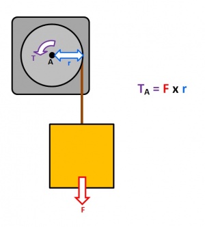
T = F * r
where
T: Torque
F: Force
r: Radius
Consider the image to the right as an example for understanding Torque. It shows a pulley connected to a motor lifting a box via a rope. The torque will act on the point A.
The box will pull down with a force:
F = m * g
where
F: Force
m: Mass
g: Gravity of Earth
The gravity of Earth is 9.81 m/s2.
Let's assume the mass M of the box is equal to 10 kilos.
The force F is then calculated like this:
F = m * g = 10 * 9.81 = 90.81 kg * m/s2 = 90.81 N.
Now, the final step to calculating the torque is to multiply the force F by the radius r (the distance from point A to the edge of the pulley.)
Let's assume the radius r is equal to 0.1 m.
The Torque will then be calculated like this:
T = F * r = 90.81 x 0.1 = 9.81 Nm.
Step 2.2 Calculate the needed power
P = T * ((2 * pi * N) / 60)
where
P: Power
T: Torque
N: Speed
If the Torque was calculated to 9.81 as in the example above and the speed was assumed to be 10 RPM, the power is calculated like this: P = T * ((2 * pi * N) / 60) = 9.81 * ((2 * pi * 10) / 60) = 10.27 Watt
