Cold Saw/V1 Design Rationale
Basic Concept
A blade rotates. The blade and/or workpiece move toward the other. The blade cuts the workpiece.
Notes: The blade should move toward the workpiece in order to facilitate angled cuts which would otherwise require rotation of the workpiece about the vertical axis, which is practically incompatible with linear workpiece feed (imagine having to move around heavy linear feed equipment at the side of the cold saw for every angled cut)
Features
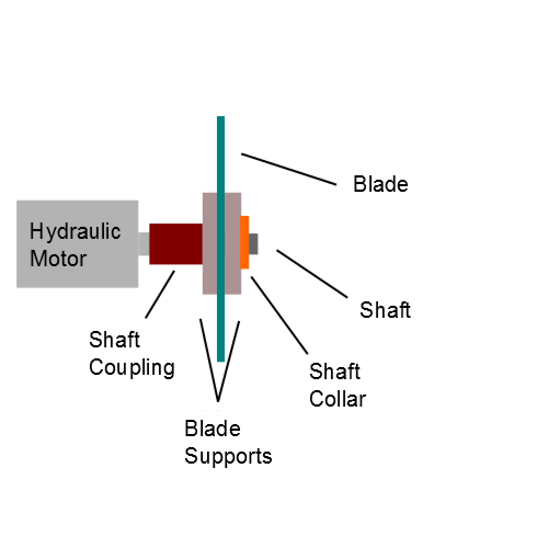
- Hydraulic Direct Drive (to provide high torque and low speed operation without complex transmission)
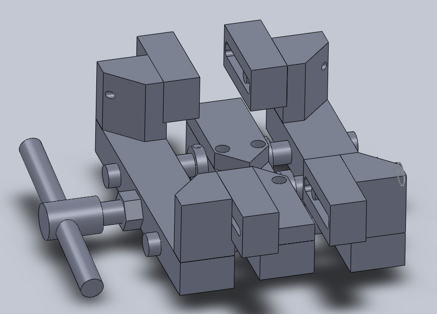
- Auto-Centering Vise (to improve cut quality and to fit more workpiece sizes and shapes)
Notes: The shaft collars prevent the shafts and threaded rod from moving under friction and clamping tension, respectively. The thrust washers minimize friction caused by the rotation of the threaded rod's shaft collars under clamping tension.
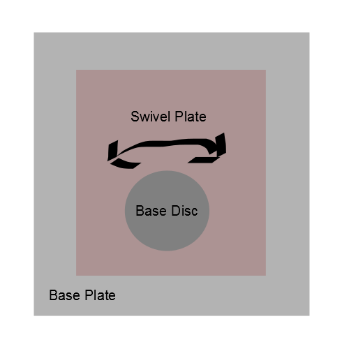
- Swivel Head (to allow angled cuts)
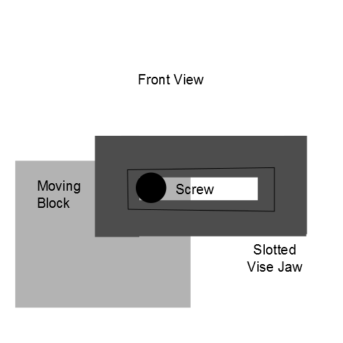
- Adjustable and Removable Vise Jaws (to accommodate variety of workpiece shapes and dimensions)
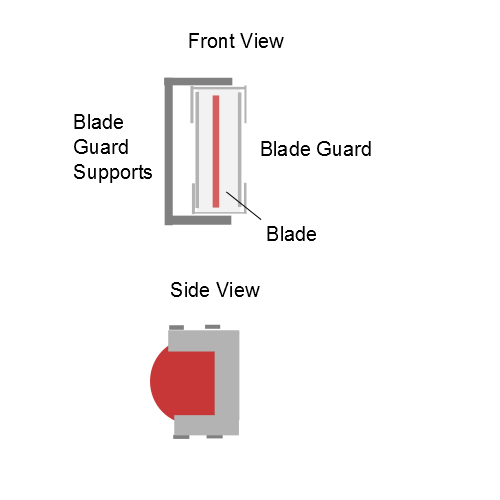
- Fixed Blade Guard (to protect against unintended blade contact during operation)
- Forward and Backward Drive Stops (to prevent cutting into vise and to hold blade in mid-air while mounting the workpiece)
Uniform Part Dimensions
- Plate: 25.4mm x 304.8mm (Base Plate, Swivel Plate)
- Flat Bar: 76.2mm x 50.8mm (Shaft Block, Fixed Block, Moving Block)
- Flat Bar: 25.4mm x 127mm (Support Bar, Bridge Bar, Interface Bar)
- Flat Bar: 3.175mm x 25.4mm (Blade Guard Support)
- Flat Bar: 1.6mm x 152.4mm (Blade Guard)
- Round Bar: 152.4mm DIA (Base Disc)
- Round Bar: 127mm DIA (Blade Mount Disc, Shaft Collar with Axial Tensioning)
- Round Bar: 50.8mm DIA (Shaft Coupling, Shaft Collar)
- Round Bar: 31.8mm DIA (Shaft)
- Round Bar: 8mm DIA (Pin)
- Setscrew: M8x1.25 THREAD
- Bolts and Nuts: M12x1.75 THREAD
- Threaded Rod: M30x3.5 THREAD
Uniform Mounting Dimensions
- Swivel Mechanism
Base Disc Mounting Rectangle Sides: 60mm x 110mm
- Vise Mechanism
Vise Mounting Rectangle Sides: 40mm x 90mm
Center-to-Center Distance Between Vise Shaft and Threaded Rod: 95mm
- Rotary Support Mechanism
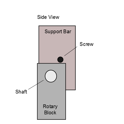
Center-to-Center Distance Between Support Block Screws: 55mm
- Drive Mechanism
Interface Mounting Rectangle Sides: 75mm x 80mm
Hydraulic Motor Mounting Rectangle Sides: 40mm x 100mm
- Blade Guard
Center-to-Center Distance between Blade Guard Support Screws: 100mm
Clamp Threaded Rod and Shafts Positioning
- The workpiece must be secure during operation.
Therefore the cut must occur near the center of the clamping volume.
- The blade must not contact the Threaded Rod at any cut angle. The Threaded Rod is at the center of the clamping volume.
Therefore a space must exist between the blade bottom-out and Threaded Rod at all cut angles.
- We want the clamp volume to be as close to the Baseplate as possible for minimizing material usage and improving Fixed Block rigidity. Lower height of blade bottom-out permits lower working volume, hence allows the clamp volume to be designed closer to the Baseplate. Below the blade bottom-out plane must be a space, then the Threaded Rod.
Therefore the Threaded Rod must be mounted as close to the Baseplate as possible.
- The shafts must balance the Threaded Rod's driving force and the workpiece's reaction force such that the Threaded Rod and Moving Block do not bend.
Therefore the Shafts must be mounted between the middle of the Threaded Rod and the middle of the clamp volume's height.

