Cory Shenk's Log
June 6, 2013: Truck (Rear)
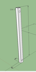
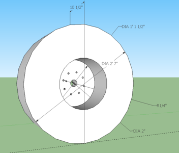
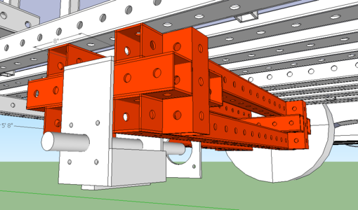
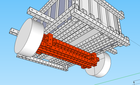
To complete the truck's rear wheel mount and axle I used the quick attachment component from this file, File:Microtrac preliminary.skp along with the hydraulic motors.
The wheel mount was found on the wiki page, File:Wheelmount - edited 5-26-13.skp .
I am still working on adding the leaf springs to the rear. Will post those as I complete them.
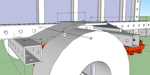
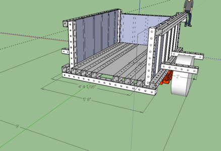
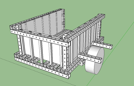
- Here are some snapshots of various components from the rear truck design. (Roll over the pictures for short descriptions)
- It seems that each quick attach system will need to be custom fit for whatever wheels are being used. That is, unless we can come up with a simple design for constructing our own.
- The "skin" or cover is drawn as 1/8" sheet metal which may be excessive. I added 1" rods that are inserted into holes in the frame to add stability since there is a likely chance of someone using the cover as a step into the bed. For use as a step, 1/8" metal may be perfect.
- The angles in the cover are drawn simply because I could not figure out a way to quickly draw an arch. It is possible that if the cover was thin enough to be flexible that it could be attached to one end (the extending beam) and bent over the plate at the arch's highest point, attached and then bent to the other beam.
June 5, 2013: Truck (Rear)
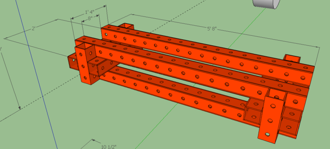
-Constructed the axle with 4" square tubing. -Made the truck bed wider, slightly over 4' to allow loading of standard size plywood. -Added 2" square tubing for rigidity in sides. Hopefully they are available, or another solution will be needed. -Still have to design wheel hubs. Bent rebar would be fast, but not modular. I am thinking that I will stack two 4" tubes on top of each other which will allow clearance and then lay flat metal across. This area is not load bearing. There could be a solution far lighter and cheaper not using metal.
MicroTrac: Tracks
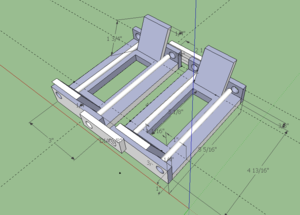
The tracks that I had been working on were scaled down from the tracks off of the LifeTrac which was incorrect. Here I have drawn the component with the correct sizes for the track that will fit to the MicroTrac. I was unable to figure out how to include the dimensions for the holes; they are all 3/8" in diameter. The rebar pieces are all #2 (1/4").
I tested the rotation and it appears that even if the track components were both to rotate at a 45 degree angle they will still not interfere with each other. In the case of the tracks, they should never rotate that far.
The attachment/adjustment component should still work with this design. It will have to be redrawn to fit this new model.
While thinking about the adjusting and attaching I have wondered if it would be a good idea to have two or four points for adjustment similar to snow chains on large trucks.
June 4, 2013: MicroTrac (Tracks)
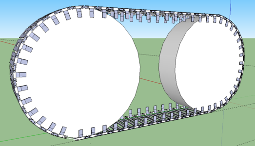
Completed tracks for MicroTrac with proposed attachment/adjustment component.
Changes
Modified track with completed track component and proposed attachment/adjustment component.
