CEB Press/Manufacturing Instructions/Controller Box/Automation Prototype II
This is 2010 continuation of work from 2009.
CEB Automation Strategy, the first Technical Paper - is found at the project management site at Open+Pario.
Overall Design for Electronics and Sensors
Solenoid Valves
This is the critical and the most expensive component of the controls. Solenoid valves must be rated for 25 gallons per minute and 2500 PSI.
- Dalton Hydraulics is the initial source to check - [1] - What amperage is required? 3 amps according to spec sheet.
- Subplate for valves - [2]
Arduino Controller
- See previous work on CEB Automation
- Arduino tutorial from Adafruit Industries - [3]
Basic Design
Control Code
- Zeroing
- One brick pressed at a time
- Continuous pressing
- Accommodate sensing
- Accommodate timeout
Solenoid Drivers
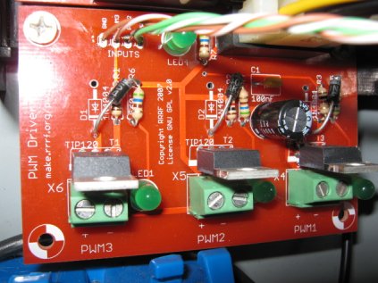
We are using [PWM Driver v1.1] boards from the RepRap project to control the solenoids in The Liberator. Two are needed to accommodate 5 channels: up-down on main cylinder, left-right on secondary cylinder, and one shaker turn-on.
- Makerbot Store
- instructions
- Make sure to address the known bug in assembly (incorrect diode placement). Here is the board after diode placement was corrected:
Only 3 channels, but otherwise perfect. We used 2 of these boards, since we need a total of 5 channels.
Probably good to use two of these and an Arduino or similar generic board for the moment and put off a dedicated PCB for someday.
BTW, Makerbot Industries is a pretty good example of a business based in open source hardware.
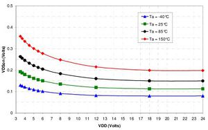
Replacement MOSFET
This should be a drop in replacement for the TIP120 darlington drivers with all round better performance. 32A, 100V max and only GBP0.87 each in small quantities:
We ended up using these since we're in the USA:
- [4] - easier to get in the USA
See discussion at the RepRap forum as to why the above choice fails, and solution - suitable MOSFET for inductive loads.
Discussion on why the replacement MOSFET is desired over the initial current driver
Resulting success with the protected MOSFETS:
Magnetic Sensors
- Hall Effect Sensors - [5]
- Example of Arduino-based Hall Effect Sensor at RMIT - [6]
- Read this thread on wiring up a Hall effect sensor
- US1881 - [7]
- the sensor was purchased from [Sparkfun
http://www.sparkfun.com/commerce/product_info.php?products_id=9312], see [datasheet http://www.sparkfun.com/datasheets/Components/General/Hall-US1881EUA.pdf]
- The pins are +,-, OUT reading from top (printed / smaller face)
- In addition, the output is "Open Drain" - this means you need a "pull up" resistor on the output (10K connected to +)
- Also, this model is "latching" which means it turns on from one pole, and off by the other, remembering it's state in the meantime. (mount the magnet so both poles pass the sensor. - not sure that's ideal, but it's the only model SF sells.)
Modular Electronics Case and Plugs
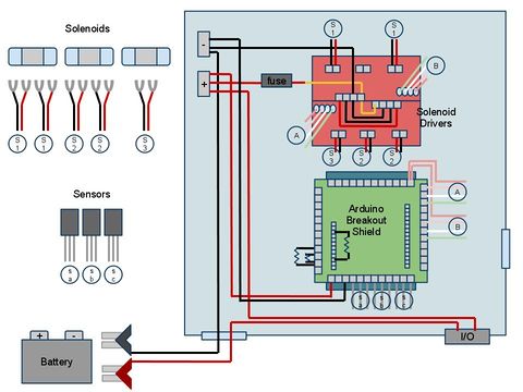
Here is a wiring diagram from James Wise, who is also prototyping the controller remotely:
Other Parts/Supplies
- An arduino shield, or small circuit board superposed on top of Arduino for easier workability, is useful in our case. We got the Arduino breakout shield v1.4 kit from Makerbot Industries. This kit required soldering.
- Potting Compound
- Molex Connectors - ?
Accessories
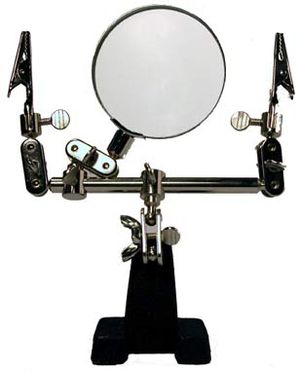
- Helping Hands Tool - [8]
Debugging
- PVC tube housed sensor. Silicone caulk sealed the sensor inside. Bad idea. Silicone never dries inside. There was a loose connection, so I freed the sensor and encapsulated again.


