Cory Shenk's Log
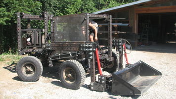
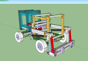
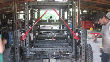
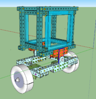
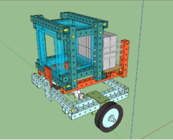
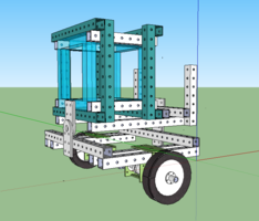
LifeTrac v5
- Sketchup File: File:LifeTrac4 (v8).skp
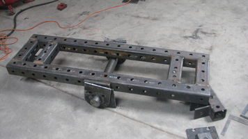
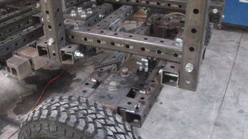
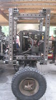
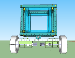
Rear Module
- Ground-hug Pivot
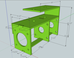
- Power Cube Module
- Rear to Cab
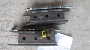
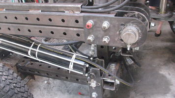
Quick Attach for Bucket and Forks
Loader Arms
Other -or- Notable Points of Concern
- Hole Alignment
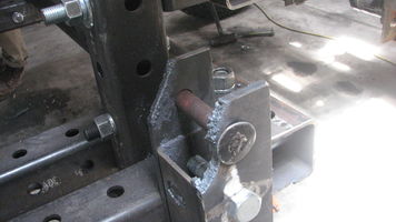
- Strength of Joints Near Pivot
- Clearance
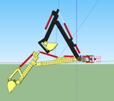
Backhoe
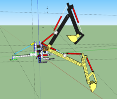
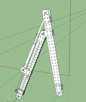
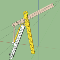
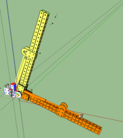
- This is the most recent version of the backhoe that I have upon the end of 6 in 60: File:Backhoe deep dig.skp
- We were never able to completely build it but we did complete sections and components. Check Leandra's Log and Luca's Log for any other information. We spent a decent chunk of time working on these together.
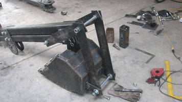
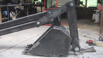
Bucket
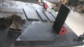
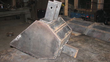
- Parts for the body of the bucket. I used three pieces that were 4 inches wide as you can see in the photo. Two should be replaced with an 8 inch wide piece of the same length. It reduces the amount of welding required and adds strength to the bucket.
- You can see two pieces have already been welded. This should be cut out of one piece of steel.
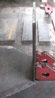
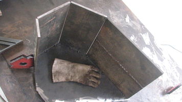
- I allowed myself extra room on the pieces that I cut for the sides of the bucket. This allowed some wiggle room when assembling the entire thing.
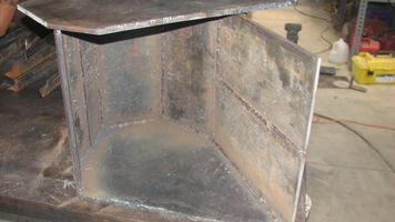
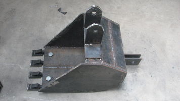
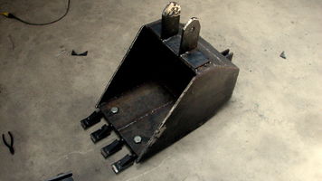
- Step by Step in Photos
- The connection points should be revisited for better attachment to the stick. See Stick Design.
- There was often physical conflict where points attached that had square corners (in the case of the bucket and in other areas, usually cylinders). It might be a good practice to simply always notch them off or round the corners with the torch, or fabricate a rounded blade for the iron worker.
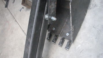
- The teeth of the bucket are bolted on so that they can easily be removed. This seems unnecessary, especially in a final version.
- I cannot determine how the shape of the bucket will affect its performance. This will need to looked into upon completion.
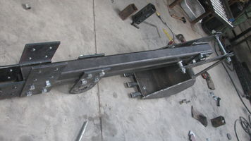
Stick
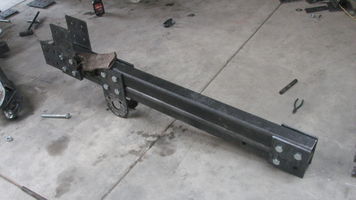
- Although we never reached the point of assembling the entire Boom and Stick to the Pivot, my guess (based off of many experiences in that workshop) is that there would have been conflict with the bolts and cylinders within the range of motion.
- To limit the amount of times that this occurs it would be beneficial to draw very exact models of bolts, washers, nuts, etc. Included with these should also be cylinders of various sizes, especially the sizes that would be used frequently.
- One variable that would be tricky account for is the way that beams and plates fit together.
- Is it possible to create warehouse pieces that include variables like these?
- 1
- 2
- 3
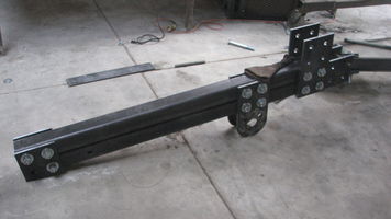
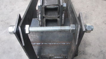
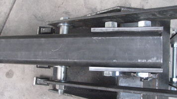
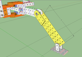
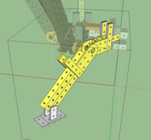
- As you can see in photos 1, 2, and 3, the triangular design that allows greater range of motion for the bucket had to be made wide to clear the bolts. This resulted in a lot of side to side movement of these pieces which is not ideal, especially under load.
- One possible solution would be to weld the two beams instead of bolting. This would allow the triangular component to rotate along the side of the stick, reducing the play.
- 4
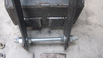
- If bolts are still used then the method of connecting the pieces needs to be addressed. We used threaded rod because we were in a rush and did not have the proper materials on hand. Threaded rod is decidedly weaker than a smooth rod. A tractor pin, or its equivalent, would be better, but it is still a great distance to span.
- 5
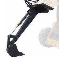
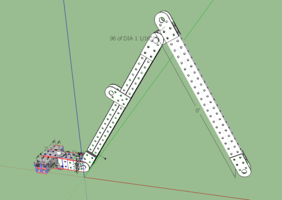
- This design employs 4 points of rotation. I was attempting to mimic the designs that I found in most commercial backhoes.
- 6
- 7
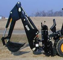
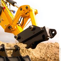
- Here are some photos that I referenced from a quick Google search:
Pivot
Cylinder - [1]
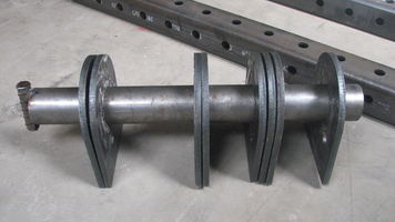
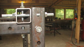
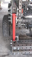
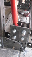
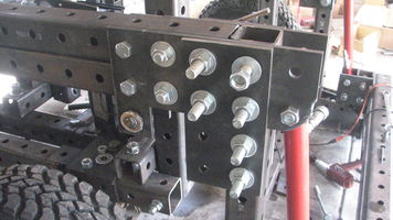
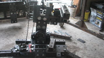
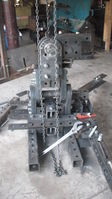
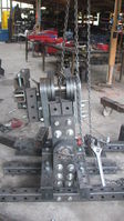
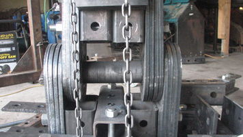
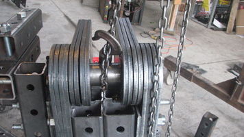
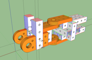
- The greatest difficulty with the pivot (and every other component we tried to build) was that the holes did not line up which made assembly difficult. The pivot had many areas that required bolts to pass through along with two three inch pins. This exacerbated the problem.
- We found that the best way to assemble was to build the pivot plates AROUND the pin and then bolt the plates to the corresponding tubing.
- The collars cut for the pivot plate were slightly different in width. This caused an irregularity in plate width once they were welded in place.
- The greatest challenge that we had with the pivot was coming up with a design to make the pivot move from side to side. Commercial backhoes have a cylinder that runs in between the top and bottom of the pivot and connects to a "C" shaped piece. Due to lack of time we were not able to come up with anything that would mimic this in design or functionality.
For the Future
- make sure the holes align
- build around the pin
- streamline the pivot (it is very heavy)
- Design with side to side motion in mind
July 19, 2013
Today is the last day of my dedicated project visit. We finished up the sixth LifeTrac yesterday, loaded it on a trailer, and sent it on its way to New Orleans to Our School at Blair Grocery. I calculated my hours for the 10 day design and build and they totaled at 130. Obviously I did not have much extra time to keep my log updated with photos from the build.
Upon my return to Kentucky I will take the time to upload any and all relevant information regarding 6 in 60 and the tractor build.
It will be hard to explain this experience to others when I get home. It was trying, difficult, and incredibly rewarding all at once. I greatly appreciate all of the hands on experience that I gained, resulting in learning many new skills.
Whether or not I return to Factor E Farm is hard to determine. However, I am eager to continue collaborating from afar. And that is the beauty of this project and the experience of participating in a dedicated visit; we can gather here for a time and then spread out across the country and the world. As I told Ian last week; its like a potluck, but with technology.
July 10, 2013: LifeTrac
File:LifeTrac4 rear v4 PivotDemo.skp
July 9, 2013: LIfeTrac
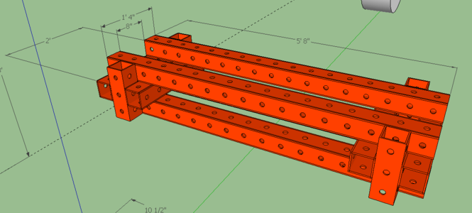
Up to date file of the rear for the LifeTrac. This will be QA'd tomorrow. File:LifeTrac4 rear v3 40cube.skp
This warehouse file has color coded bolts with dimensions. File:Warehouse.skp
File:LifeTrac4 rear v2 40cube.skp This version has the enlarged PowerCube.
July 8, 2013: LifeTrac4
- First concept for the rear of the LifeTrac4: File:LifeTrac4 rear v1.skp
- This is not complete but I am uploading it for collaboration purposes
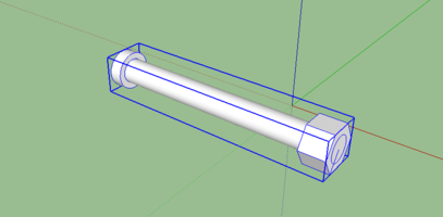
- Rough dimensions of a 9 inch bolt: File:9inch Bolt.skp
June 26, 2013: Bulldozer Wheel
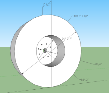
- No picture, sorry, but this is the file for the big ol' metal wheels. It is incomplete but shows the proportions for the tred, wheel plates and the dimensions for the hub. Chris is working on the DXF files and completing a SketchUp file for the entire design.
June 25, 2013: Backhoe
Most recent version of the backhoe design. The side to side motion is still up in the air for now.
June 22, 2013: Backhoe
- Most recent and nearly final backhoe design.
June 18, 2013: Backhoe Bucket Action
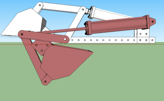
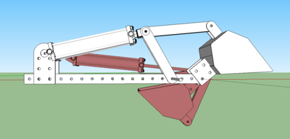
- I took the Stick and Boom from [[2]] along with the bucket from [[3]] and came up with a working model to show that the hydraulic works with the bucket and the arm while also allowing the needed range of motion for regular backhoe work.
- NOTE:There are errors within this file but it demonstrates a popular design used for the bucket from images that I found on the web. Below is one example that I looked at:
Here are the results:
- The stick needs to be changed so that it is doubled up.
- The pivot points on the bucket need to be attached in a more realistic way.
- The bucket needs teeth.
- The points of connection for the hydraulic cylinder needes to be scaled down to 1". Marcin informed me that the plate with the 3" hole is overkill.
- Include the pivot point where the stick will connect with the boom.
- Probably other things that I am missing.
June 18, 2013: Backhoe (Stabilizer Arms)
Stabilizing Arm1: Right angle
- This is a rough sketch up for a potential stabilizer arms for the backhoe: File:Backhoe stabilizerarms1.skp
Stabilizing Arm2
- This one seems better in concept, however, I am uncertain about its structural integrity.
- This version also includes potential spots for attaching the hydraulics along with the range of the boom.
- Full file can be accessed here: File:Backhoe stabilizerarms2.skp
June 17, 2013
MicroTrack: Adjusted Track Component
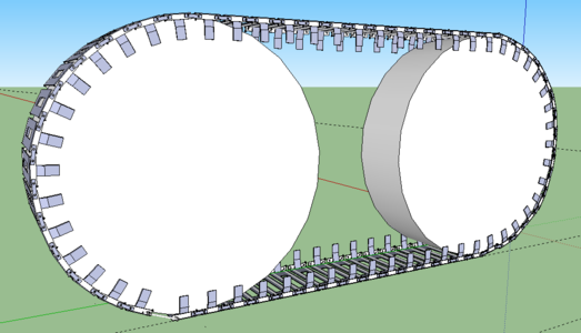
- Drew out the wider track components for the MicroTrac. This shows the component linked together.
- This picture shows the new dimensions of the component.
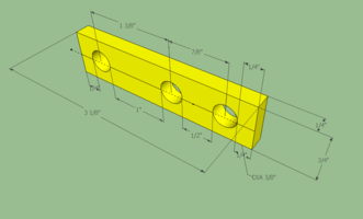
- Dimensions for the connector piece.
- All three images can be accessed through this file: File:MT tracks 6inch.skp
Truck Hydraulics Diagram
- Chris and I determined that he will will include a Male Quick Connect part on the foot pedal of the truck cab that will be attached to the wheel motors.
- I will complete my schematic up to the female QC that will attach to that Male QC.
- This follows with the module concept.
June 15, 2013: Backhoe Pivot
Cylinder to use: 3"x8" - [4]
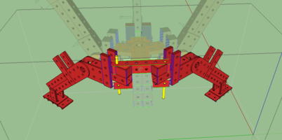
- Put together a quick design for the pivot of the backhoe arm. Not sure if anyone is working on one. If so, didn't mean to step on anyone's toes or double up on something.
- Needs stabilizing arms/legs and a design for the Quick Attach to the LifeTrac.
June 14, 2013
Backhoe
- Found a rough concept for the backhoe to work off of.
- Redesigned the stick to add a wider range of motion like those found in commercial backhoes.
- Used hydraulics found on the wiki to determine the retracted and extended range.
- Used the same hydraulics on the boom. Found that shorter hydraulics will be needed.
- Marcin and I looked at the arm and decided to make shorten each arm to 6ft. This will change the hydraulic size also.
- The pivot needs work; more strength and also space to add stabilizing legs.
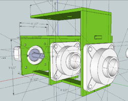
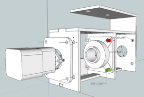
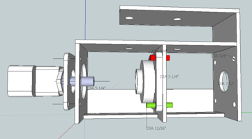
Quick Attach Wheel Mount
- This is the most current wheel mount for the 3" bearing. File:WheelMount 3inch bearing.skp
- This is the most current wheel mount for the 1 7/8" bearing. File:Wheelmount 1and7 8 bearing.skp
June 13, 2013:Quick Attach Wheel Mount
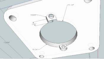
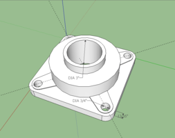
- Finished adjusting the placements and sizes of the holes for the 3 inch bearing. Had to nuts around for a while to get everything lined up. File:WheelMount 3inch bearing.skp
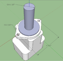
- This picture shows the alignment of the bearings with the PTO motor in its adapter plate.
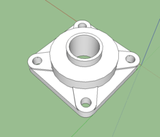
- Drew this 1 7/8" bearing using the specifications from Surplus Center.
- This part can be found here: [[5]]
- Used the new bearing to align the holes and adjust their size for the 1 7/8" bearing. File:Wheelmount 2inch bearing.skp
- Still need to adjust the connection tabs for the entire structure. Will collaborate with Lucas on that one.
June 12, 2013: Quick Attach Wheel Mount
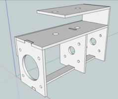
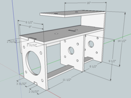
- Pulled this file off of the MicroTrac. Gary had made adjustments to the overall dimensions to correct it. I added the interlocking portions between the plates.
- Still need to verify that the holes are the correct size and spaced properly.
File:Wheelmount Updated 6 12.skp
Wheel Mount and Components
- This shows the PTO motor with the adapter plate along with the 3 inch bearing all in place on the adjusted Wheel Mount.
- Same components from a different angle.
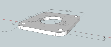
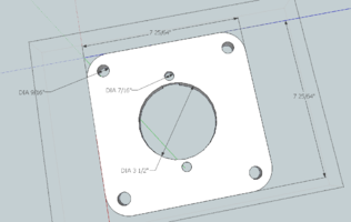
Adapter Plate
- This is the file for the adapter plate: File:PTO AdapterPlate.skp
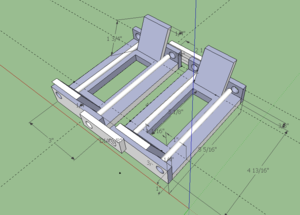
- The follow three images show different angles on the adapter plate along with dimensions.
June 11, 2013: Quick Attach Wheel Mount
- Drawing of the PTO motor with dimensions.
- Taken from Surplus Center where we will be purchasing the part.
- Link to the part: [[6]]
- More specs: [[7]]
- The crucial dimensions are included in the drawing which will determine the location and size of the holes in the Quick Attach Wheel Mounts.
- Created a scale model of the 3" bearing that will be used for the axles using the specs from Surplus Center
- Item# 1-215-48-4 [[8]]
- Detailed Specs found here: [[9]]
- NOTE: the specs indicate that the bolt is 11/16 for attaching the bearing plate. Could not determine if this was the size of the hole or the bolt. If it is the bolt then there must be some amount of tolerance, so I drew the holes in the piece as 3/4 which will align with the 3/4" holes that will be made in the Quick Attach Wheel Mount.
June 10, 2013: Dump Truck
- I've been tasked with re-designing the bed of the truck so that it dumps. I'm designing a dump truck. Since I have never built a truck bed or a dump truck bed I spent a little time doing some Youtube research. There are a great deal of folks who have built their own dumping truck beds. Some use a winch system. It is a cute idea and would work well if you were hauling dry leaves or empty soda cans. However, I intend for anyone who may build this thing to be able to do some really serious hauling and dumping.
- Here are some videos of different hydraulic arms.
[[10]]
[[11]]
[[12]]
- I've come up with two different designs for the dumping bed.
- Version 1 has a bed that 'nests' into the original frame of the bed. The hinge point is shown with an excessively long pin. Most hinge points are much less robust. This entire hinge may be excessive, however, it would be quite strong. One drawback that I see already is that there is a small lip where dirt, stones or whatever is being dumped, would catch.
- Another issue is where to place the hydraulic arm, or hoist system. There is room underneath but there will probably need to be more structural elements added to support this. The design is already a huge amount of metal.
- Version 2 has a dumping system that rests on top of the frame. The hinge joint is a two point system. By having the bed rest on top of the frame, more room is created for attaching the lifting system. It also cuts down on the amount of metal needed.
- This version is not entirely completed yet. Some supporting beams still need to be placed in the dumping bed but it conveys the concept clearly at this point which is the main objective for now.
- Finally, here is the link to the SketchUp file: File:Shenk truck back.skb
June 10, 2013: Truck (Rear)
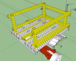
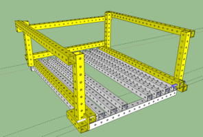
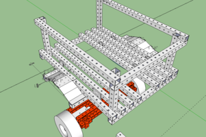
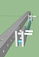
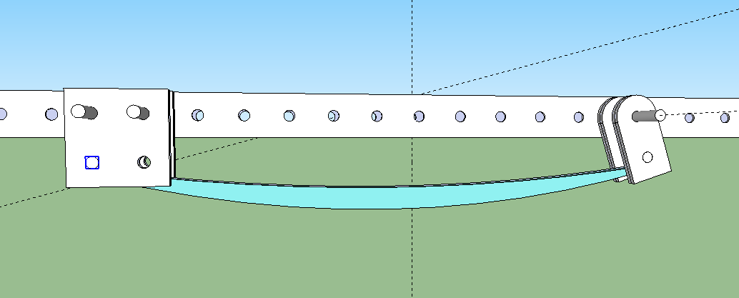
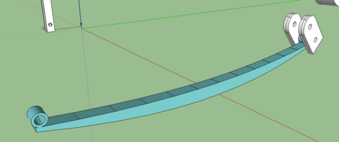
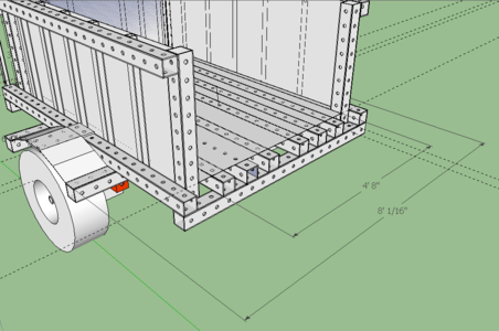
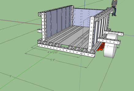
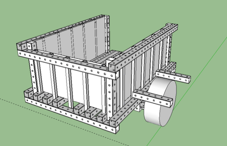
- Updated truck bed. Sidewalls and smaller posts have been removed. The leaf springs have been attached. I needed to add a component to the one end so that the holes lined up for attaching. Snapshot is below of entire bed followed by close ups of the leaf spring when attached.
- Same design but built with new warehouse parts. File size is now smaller and the entire bed more manageable
- File:Shenk truck back.skp
June 7, 2013: Truck(Rear)
Most recent file of the truck's rear design:
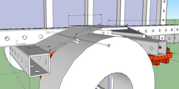
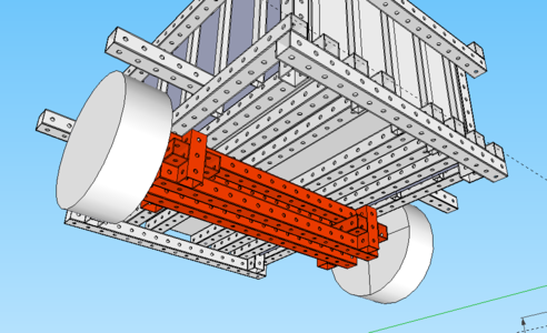
- Shows the leaf spring with the leaf spring attachment component. Note that the attachment component is doubled up.
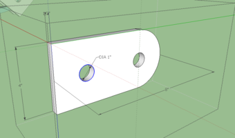
- Adjusted one of the pieces from the warehouse. The square ends that were there would have interfered with the flooring of the bed. When used to attach the leaf spring this component is doubled up; two on each side and then bolted to the frame of the truck.
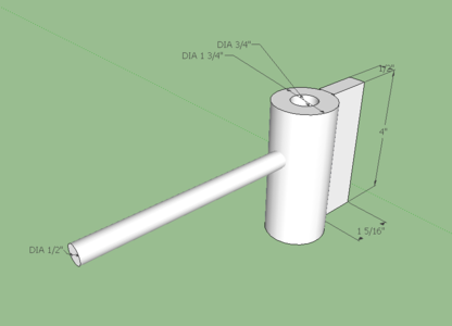
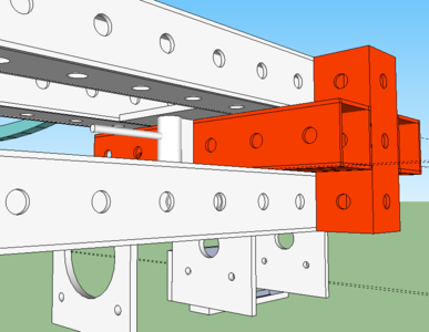
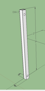
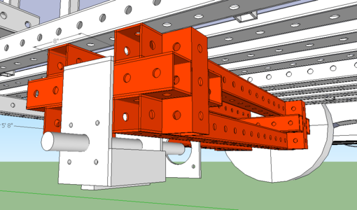
Created this piece based off of what I found on the LifeTrac in the shop. This spacer will keep the Quick Attach wheel mounts from moving in and out. The rod projecting horizontally from the vertical tube would be rebar, its purpose being to hold the piece in its proper place as it is bolted in. Many of the measurements are variable and could be easily adjusted to whatever material is available at the time.
- I had to modify the rear of the truck to match with the joint that Jordan is designing. This allowed me to make the bed wider which provides more room for hauling more material.
- Here is the current SketchUp file for the rear of the truck. It includes all the various components and their dimensions. File:Shenk truck back.skp
June 7, 2013: MicroTrac
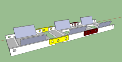
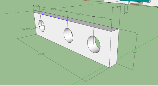
- The blue link shows one attachment point while the yellow link on the right shows the second. This design allows versatile adjustment along the entire length of the track.
- Shows the dimensions of the link piece. I had to draw lines on the piece to be able to include the On Center dimensions of the holes.
- Width of the link piece could easily be adjusted to be thicker or thinner as needed.
- I tested the rotation and there should not be any interference with range of motion between the link and the track component.
- File:MT tracks proper.skp
June 6, 2013: Truck (Rear)
To complete the truck's rear wheel mount and axle I used the quick attachment component from this file, File:Microtrac preliminary.skp along with the hydraulic motors.
The wheel mount was found on the wiki page, File:Wheelmount - edited 5-26-13.skp .
I am still working on adding the leaf springs to the rear. Will post those as I complete them.
- Here are some snapshots of various components from the rear truck design. (Roll over the pictures for short descriptions)
- It seems that each quick attach system will need to be custom fit for whatever wheels are being used. That is, unless we can come up with a simple design for constructing our own.
- The "skin" or cover is drawn as 1/8" sheet metal which may be excessive. I added 1" rods that are inserted into holes in the frame to add stability since there is a likely chance of someone using the cover as a step into the bed. For use as a step, 1/8" metal may be perfect.
- The angles in the cover are drawn simply because I could not figure out a way to quickly draw an arch. It is possible that if the cover was thin enough to be flexible that it could be attached to one end (the extending beam) and bent over the plate at the arch's highest point, attached and then bent to the other beam.
June 5, 2013: Truck (Rear)
-Constructed the axle with 4" square tubing. -Made the truck bed wider, slightly over 4' to allow loading of standard size plywood. -Added 2" square tubing for rigidity in sides. Hopefully they are available, or another solution will be needed. -Still have to design wheel hubs. Bent rebar would be fast, but not modular. I am thinking that I will stack two 4" tubes on top of each other which will allow clearance and then lay flat metal across. This area is not load bearing. There could be a solution far lighter and cheaper not using metal.
MicroTrac: Tracks
The tracks that I had been working on were scaled down from the tracks off of the LifeTrac which was incorrect. Here I have drawn the component with the correct sizes for the track that will fit to the MicroTrac. I was unable to figure out how to include the dimensions for the holes; they are all 3/8" in diameter. The rebar pieces are all #2 (1/4").
I tested the rotation and it appears that even if the track components were both to rotate at a 45 degree angle they will still not interfere with each other. In the case of the tracks, they should never rotate that far.
The attachment/adjustment component should still work with this design. It will have to be redrawn to fit this new model.
While thinking about the adjusting and attaching I have wondered if it would be a good idea to have two or four points for adjustment similar to snow chains on large trucks.
June 4, 2013: MicroTrac (Tracks)
Completed tracks for MicroTrac with proposed attachment/adjustment component.
Changes
Modified track with completed track component and proposed attachment/adjustment component.
