Open Source Golf Cart
Intro
Work Doc
Update from Anthony Douglas, march 22:
ok so the motors we chose from surplus center have a 5.4 cubic inch per rotation displacement, which with a typical spare wheel automotive wheel's diameter, and the rpm of the engine in the power cube, and the cubic inches per rotation of the pump in the power cube, is a good displacement.
However they have a tapered shaft with 1 inch diameter at the base of the taper. There are apparently totally no wheel hubs that fit this shaft available off the shelf. The wheel hub is the piece that connects the shaft of the motor to the wheel. The wheel is the metal piece with the rim attached, and the tire.
Points: 1. What happened to the wheel units used in the tractor etc?
2. This gearing ratio between the engine in the power cube and the hydraulic motors is going to be a perpetual problem. To have no variable transmission has been a problem for a long time in several ways, and leads to greatly reduced power output from the power cube, and less general purpose nature of the power cube. However off the shelf variable displacement hydraulic pumps appear to be too expensive, like a thousand bucks each for one capable of 3000 psi output. Any kind of gearbox would also be complicated and add expense, and require redesign of the power cube, and wear out. I have discovered that there is a variety of variable displacement hydraulic pump called the variable displacement vane pump, which are available for about $300 usd each, on e.g. amazon and other sources (so they are common). However, the max pressure tends to be far too low, about 1000 psi rather than the 3000 that is more commonly the standard in hydraulic equipment of this nature.
3. There is a possibility of machining a small 1/8 inch thick adapter to adapt the 1 inch diameter shaft to the 1 1/4 inch diameter tapered wheel hub, however this looks like it would wobble and slide in various was with high forces, leading to serious issues over time. It could be lathed or milled.
4. This is a classic problem, there are often parts that we need which are not available off the shelf. Sometimes complex, sometimes simple. To be able to make what we draw on the screen as with 3d printing but in steel and to high enough tolerances would be extremely valuable. Not just in these special cases, but to greatly increase the foundational power that we have. This is a form of infrastructure building that I believe we should actually budget time for doing. It may take the form of simply getting reasonably practiced at doing lost pla casting with block molds using calcium aluminate cement (which is like plaster but good for steel casting). That could work fine in this case, but when the time comes to use it we are not ready; we instead face an uphill climb that is not worth it for this particular project. Yet it has extremely broad applications. So I believe it is effective infrastructural work.
However the output of this process would be rather imprecise, not least because the printing is a bit imprecise. What we need is to be able to make more accurate parts. If we could make the mold directly through machining that would help a lot. This is what I am working on with rugdmmac.
5. As long as the taper is the same angle, it may be possible to use the hub made with the 1 1/4 inch diameter hub, but the displacement axially would be 1/4 *8 inches, which is 2 inches. That is too much. So no that's not really workable.
6. the most promising approach appears to be to me to get hydraulic motors that have standard shafts. That's what we want, to be able to reuse them for other things anyway. What are the other motors on site at ose, which had previously been purchased? Why do we not have some on hand that we can use instead of buying more?
The splined shaft and the 1 1/4 inch tapered shaft, both with 1/4 inch keys seem to be good. Hubs for cars usually use splined shafts, however none of the motors available on amazon or surplus center use the splined shaft. they use either cylindrical shaft with key or tapered 1 1/4. There are some on ebay etc. but they are expensive, and do not want to say what the diameter of the shaft is, and it does not look like it is the same.
The cylindrical with keyway, how does the bolt not loosen? it will constantly slip slightly at each rotation. there will also be some slop with radial loads or radial torques. this does not look good to me. are you sure it is not slightly tapered? Maybe you are supposed to use some kind of clamp connector such as the tapered split bushing.
Fundamentally, the tapered shaft is superior to a bolted on cylindrical shaft, if that is the choice. The nut can be tightened so that the torque is almost always transmitted through friction through the shaft. the key is only a safety device. Same with the pin on the castle nut. it also holds the wheel on there better. This is also the load bearing shaft which will bear the radial loads and the torque that arises in the planes paralel to the shaft (in addition to the torque from the motor)
I chose the tapered shaft, therefore. What remains is to find a motor on amazon or elsewhere that has about 5 cubic inches displacement, then.
ok. After searching, the motors I am finding with tapreed shafts are all $400 or more each. thats too much.
There are no hubs for 1 inch shafts with keyways, only the splined and the 1 1/4 inch tapered shaft. and the motors with 1 1/4 inch shafts are grossly overpriced. So, for whatever reason the standard parts that interface to these hubs are not usually hydraulic motors. And hydraulic motors are not that commonly attached to splined automobile hubs.
The sites with the splined hubs do not want to ever tell you what the actual diameter of the shaft is. Classic. You are supposed to enter your make and model instead. They will never give you the cad model. It isa system not made or suitable for our purposes.
We will always have these kinds of problems. We might as well get on with trying to solve it right now.
In conclusion, I recommend that the most practical approach for the very near term is simply to choose the nearest motor from surplus center with a 1 1/4 inch tapered shaft, and the power cube will have to be throttled up some for acheiving higher speeds.
https://www.surpluscenter.com/Hydraulics/Hydraulic-Motors/Wheel-Mount-Hydraulic-Motors/7-6-cu-in-White-Drive-Products-157125W31N9AAAAA-Hydraulic-Motor-9-8832-B.axd so this one is the recommended motor, and https://www.surpluscenter.com/Hydraulics/Hydraulic-Motors/Wheel-Hubs-for-Hydraulic-Motors/5-Bolt-Wheel-Hub-1-1-4-Tapered-w-Brake-Drum-1-3364.axd is the recommended hub. The five bolt pattern is common on cars. We need to be sure the bolt circle diamter is right. it says 4 1/2, which is the closest imperial of one of the standard automotive ones according to the wikipedia article on wheel sizes.
https://www.ebay.com/itm/Parker-Hydraulic-Wheel-Motor-114A-088-LS-O-1-1-4-tapered-shaft-Bunton-PL7095-/192814130130 would be a good motor. there are only 3 available. Indeed, this is why choosing standard low cost parts is critical.
To resolve this and all such problems in the future, we simply must have the ability to make at least basic mechanical parts such as the wheel hub, in a practicaly and economical way, such that we are not trying to avoid employing it. It has to be actually operational.
Aidan's Thoughts 3/31/2019
Wheel Hubs
I looked into the issue of adapting the 1" tapered shaft to a wheel. I see a few options:
- Crappy option 1: Buy a 1" tapered hub made for a bolting on a sprocket and weld or bolt on a plate for the wheel bolt pattern. These are small hubs meant for pulleys or sprockets that would most likely fail in this application
- Find a supplier of taper adapter sleeves. I found 1" to 3/4" so they are out there, as Anthony mentions.
- Use a different wheel motor. This is a chinese supplier's motor that most closely fits the needs outlined by Anthony About $150 per piece on alibaba. I don't have drawings for these.
- Adapt straight bore hubs to tapered hubs by machining them either with an expensive tapered reamer or less expensively on the lathe. These hubs are probably hardened so it would require a carbide insert boring bar if it is possible at all.
Update 6/16/19
Instead of machining a hardened, straight bore hub, a better idea is to create a Taper to Straight Shaft adapter. This can easily be machined on a lathe because you can grip the OD with a three jaw or a collet. The issue here is the keyway. Perhaps instead use three or four set screws that thread from the hub through the adapter and bottom out in the keyway.
 File:Taper to Straight adapter.fcstd
Motor Selection
Another thought I had was to use 2 sizes of motors. Low speed front motors and higher speed back motors. If this is a skid-steer cart then we would need a switch-like valve in addition to the skid-steer detent valves. The purpose of this valve would be to change the flow from front motors to rear motors. I'm imagining a ball valve or a double pole single throw ball valve. You need to still be able to skid steer so it has to be after the detent valves for left/right drive but it can't obstruct the flow of the system and it would be nice if it could still allow 4x4 even though the wheel speeds wouldn't match.
We used to do something similar sometimes on LT4 where we would disconnect either front or back motors to achieve higher flow rates and get higher speeds to move around faster IIRC. A simpler option is to use the same 4 motors but have an operator-controlled valve that can disconnect a pair of motors for higher speed operation.
Part Availability
If we have 95% of a BOM off-shelf and 5% are specially machined items then we should just manufacture and sell those specially machined items as a kit. Something like a special hub isn't that hard to produce. Heck, we could machine it from aluminum for this golf cart application. Maybe the point isn't to make every item in the BOM off-shelf but to make every item universally available i.e. we will sell it to you from our OSE store.
Part Library
Hydraulic Motor


Hydraulic valve - [1] - 1.5MB
Motor drawn from the drawings, known to be of accurate dimensions on all counts to the limits of the drawings ( the drawings provided by the manufacturer are incomplete, the motor that is bought should be measured and drawn or this file modified. the Fusion file cannot be uploaded to the wiki because only certain file types are allowed.) File:Motor drawn in f converted to fcstd.FCStd
the fusion file can be accessed here: https://a360.co/2Jn9mpJ
https://wiki.opensourceecology.org/images/1/1a/Motor_mount_plate.FCStd
Reference design


Frame and Structure


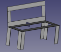
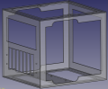
GC Bench Seat- File:GC Bench Seat.fcstd
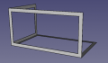
Frame - File:GC frame.fcstd
- GC motor mount.png
Motor mount - File:GC motor mount.fcstd, STEP - File:GC motor mount.STEP
- GC steering.png
Pipe - File:GC steering.fcstd
- GC front.png
GC front File:GC front.fcstd
- GC rear.png
GC rearFile:GC rear.fcstd


Photovoltaic Panel

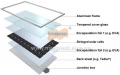
GC solar panel. See PV Panel for specs.File:GC PV panel 19.03.FCStd


Power Cube
Auxiliary (small) Power Cube v18.01 - size:kb - FreeCAD -git repo. Or wiki - File:Pcv1801.fcstd
Auxiliary (small) Power Cube Frame Assembly v18.01 - size:kb - FreeCAD -git repo.
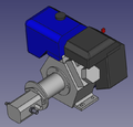
Engine coupled to Pump PC v17.11 - size:kb - FreeCAD -git repo.
- Power Cube v19.02.png
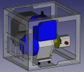
Hydraulic Tank Power Cube v19.02 - size:kb - FreeCAD - File:Power Cube v19.02.fcstd


Human Usability Features
- Seat
- Electric start
- Cab cover
- Lights
- Windshield
- Body panel
- Cargo area