File:Patented combined cycle system (watercooler).JPG: Difference between revisions
Jump to navigation
Jump to search
(Schematic showing the design of the patented combined cycle system (patent 692/MUM/2013: COMBINED CYCLE SYSTEM TRANSFERRING THE WASTE HEAT BETWEEN THE ENGINES, DIRECTLY FROM THE ENGINE(S) OR VIA THE COOLANT WATER OF THE ENGINE(S), BY MEANS OF A LIQUID...) |
(No difference)
|
.JPG&oldid=135305)
.JPG&action=edit)
Latest revision as of 10:41, 3 February 2016
Schematic showing the design of the patented combined cycle system (patent 692/MUM/2013: COMBINED CYCLE SYSTEM TRANSFERRING THE WASTE HEAT BETWEEN THE ENGINES, DIRECTLY FROM THE ENGINE(S) OR VIA THE COOLANT WATER OF THE ENGINE(S), BY MEANS OF A LIQUID ) and the placement of the PCB inside it
File history
Click on a date/time to view the file as it appeared at that time.
| Date/Time | Thumbnail | Dimensions | User | Comment | |
|---|---|---|---|---|---|
| current | 10:41, 3 February 2016 | 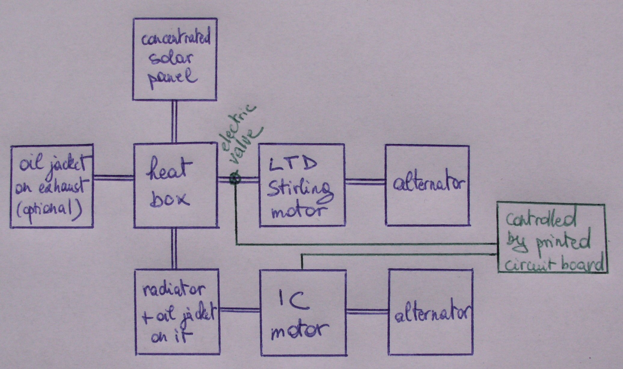 | 2,072 × 1,228 (325 KB) | OS combined cycle (talk | contribs) | Schematic showing the design of the patented combined cycle system (patent 692/MUM/2013: COMBINED CYCLE SYSTEM TRANSFERRING THE WASTE HEAT BETWEEN THE ENGINES, DIRECTLY FROM THE ENGINE(S) OR VIA THE COOLANT WATER OF THE ENGINE(S), BY MEANS OF A LIQUID... |
You cannot overwrite this file.
File usage
The following page uses this file:
.JPG&oldid=135305)