Combined cycle system PCB
Overview
- This page details a special printed circuit board (PCB) for a combined cycle system, hereby making this PCB free to use/build under the CC-By-SA license.
The PCB is intented to be used with a Combined Cycle System , consisting of
- An internal combustion engine (gasoline or Diesel engine preferably running on biofuel)
- A Stirling engine
- The Stirling engine is driven on waste heat of the internal combustion and so it is started whenever there is sufficient heat collected from the internal combustion engine. *It deactivates when there is not enough heat any more, and then restarts the Diesel engine (this is all done by means of a printed circuit board).
- The PCB is an essential component to allow a combined cycle system achieve maximum efficiency, especially if the internal combustion engine isn't fully matched to the stirling engine (and thus produces more heat than what the stirling engine can effectively use in a given period of time.
Requirements
- It can be used with an air-cooled internal combustion engine (via an attachment through the oil filter) or a liquid-cooled internal combustion engine
- The internal combustion engine also needs to have an electric start.
Workings
Here's how it works:
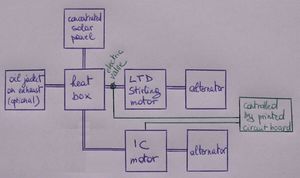
The printed circuit board automatically stops the internal combustion engine upon having the oil reach a certain temperature (say 100°C). With a gasoline engine, the stopping can be done by having the PCB preventing the spark plugs of operating (meaning the spark plug battery needs to be deactivated, or the magneto -if it uses a magneto instead of a battery). The Stirling engine can then be automatically switched on by the printed circuit board by opening an electric valve. Then, after a while, when the oil temperature has dropped considerably and is no longer able to run the alternator, the printed circuit board closes the electric valve to the Stirling engine and starts the internal combustion engine again. See the schematic of this here below:
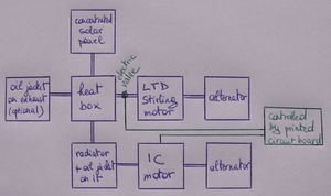
The image below shows a similar setup for when a the Stirling motor is connected, not unto piping attached on the oil filter, but on the radiator of the IC motor (obviously this is only done with water-cooled IC motors, not air-cooled IC motors).
Note that if a Diesel engine is used instead, instead of stopping the spark plugs of operating (which a Diesel engine doesn’t have), the air and/or fuel inlets need to be obstructed instead (ie using electrically openable/closable valves). Some manufacturers provide "Diesel engine shutdown systems" that could be of use here. Some notable manufacturers are:
- http://www.wyndhampage.com/technical
- http://www.dtiguardian.com/Product.php
- http://enginewatchdog.com/tm6_home.html
- http://www.amot.com/tenants/amot/documents/Chalwyn-CSX-300.pdf
- http://www.chalwyn.com/products/fuel-shutoff-valve
Notes
Make sure that if building an open-source combined cycle system using this printed circuit board, you don't violate patent number 692/MUM/2013: COMBINED CYCLE SYSTEM TRANSFERRING THE WASTE HEAT BETWEEN THE ENGINES, DIRECTLY FROM THE ENGINE(S) OR VIA THE COOLANT WATER OF THE ENGINE(S), BY MEANS OF A LIQUID (for example by using a centralised heat box, ...) If you do want to build it by integrating a centralised heat box, ... you will need to ask permission and contact the owner of the patent, to build it under a license.
Internal Links
External Links
- (for CSP): SolarFlower
- (for CSP): Sunvention International CSP
- (for CSP, non-tracking): Oneearthdesigns CSP

