Parametric Sprocket: Difference between revisions
Jump to navigation
Jump to search
| (10 intermediate revisions by the same user not shown) | |||
| Line 1: | Line 1: | ||
*http://www.thingiverse.com/thing: | *Source: '''http://www.thingiverse.com/thing:7918''' | ||
*The | =How to Design a Sprocket for Bulldozer Drive= | ||
*The sprocket generator in OpenSCAD creates a proportionally correct sprocket. | |||
*How do we know how to scale it to match our specific case? | |||
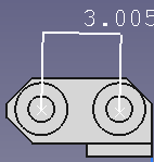
*We first design the track. We settled on pin spacing of 3", and XXH 1.5" pipe (see [[Pipe Chart]]) for the roller, with 1" pins. Thus: roller = 1.9" OD (1.5" XXH pipe), pitch = 3" (based on geometry of pins: | |||
[[File:trackpad.png|200px]] | |||
*'''Ratio of 3/1.9=1.58. Ratio of pitch to the roller is constant. | |||
*Then we generate the sprocket using 5 parameters | |||
:*1 - Number of teeth | |||
:*2 - Roller (5 units) | |||
:*3 - Pitch - 1.58x the roller size as determined by our track geometry (looks sensible, and 3" pitch was selected as a convenient distance, and 1.9" OD roller was selected as a readily-available stock material | |||
:*4 - Thickness - that is the thickness of the plate material | |||
:*5 - Tolerance - play in the distance between rollers (pitch)? | |||
*To generate a correct sprocket, we can scale the resulting design in CAD - by superposing the track piece over the sprocket to make sure the track pieces fit in the valley-to-valley distance in the sprocket (which corresponds to the distance between rollers, or pitch) | |||
:*See the [[File:Sprocketgeo.dxf]] for how the track pieces fit into the sprocket (example shows a larger sprocket than an 8 tooth sprocket) | |||
=Bulldozer 2015 Usage= | =Bulldozer 2015 Usage= | ||
{{Hint|The bulldozer from 2015 used an 8 tooth sprocket, generated with sprocket(8,5,7.5,2,0.2); in the last line of the Editor | {{Hint|The bulldozer from 2015 used an 8 tooth sprocket, generated with sprocket(8,5,7.5,2,0.2); in the last line of the Editor}} | ||
=Exporting DXFs from 3D Objects in OpenSCAD= | =Exporting DXFs from 3D Objects in OpenSCAD= | ||
| Line 13: | Line 28: | ||
:*Note: original srocket was generated using [[Parametric Sprocket Generator]] using sprocket(12,5,7.5,8,0.2); | :*Note: original srocket was generated using [[Parametric Sprocket Generator]] using sprocket(12,5,7.5,8,0.2); | ||
=Links= | |||
*Sprocket geometry for a correct sprocket pitch and roller diameter - example - [[File:sprocketgeo.dxf]] | |||
:*Uses [[Sprocket Generator]] | |||
[[Image:dxfexportex.jpg|400px]] | [[Image:dxfexportex.jpg|400px]] | ||
Latest revision as of 16:00, 25 December 2020
How to Design a Sprocket for Bulldozer Drive
- The sprocket generator in OpenSCAD creates a proportionally correct sprocket.
- How do we know how to scale it to match our specific case?
- We first design the track. We settled on pin spacing of 3", and XXH 1.5" pipe (see Pipe Chart) for the roller, with 1" pins. Thus: roller = 1.9" OD (1.5" XXH pipe), pitch = 3" (based on geometry of pins:
- Ratio of 3/1.9=1.58. Ratio of pitch to the roller is constant.
- Then we generate the sprocket using 5 parameters
- 1 - Number of teeth
- 2 - Roller (5 units)
- 3 - Pitch - 1.58x the roller size as determined by our track geometry (looks sensible, and 3" pitch was selected as a convenient distance, and 1.9" OD roller was selected as a readily-available stock material
- 4 - Thickness - that is the thickness of the plate material
- 5 - Tolerance - play in the distance between rollers (pitch)?
- To generate a correct sprocket, we can scale the resulting design in CAD - by superposing the track piece over the sprocket to make sure the track pieces fit in the valley-to-valley distance in the sprocket (which corresponds to the distance between rollers, or pitch)
- See the File:Sprocketgeo.dxf for how the track pieces fit into the sprocket (example shows a larger sprocket than an 8 tooth sprocket)
Bulldozer 2015 Usage
![]() Hint: The bulldozer from 2015 used an 8 tooth sprocket, generated with sprocket(8,5,7.5,2,0.2); in the last line of the Editor
Hint: The bulldozer from 2015 used an 8 tooth sprocket, generated with sprocket(8,5,7.5,2,0.2); in the last line of the Editor
Exporting DXFs from 3D Objects in OpenSCAD
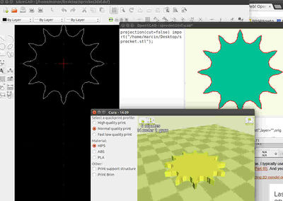
- Exporting DXFs - [1] - essentially - load and flatten, then export DXF
- Note: stock Export DXF does not work for 3D files - they need to be projected first.
- To project - projection(cut=false) import("sprocket.stl"); STL file must exist in same directory
- Sample file for exercise in OpenSCAD - the sprocket STL and the .scad file that loads the STL and does a 2D projection. Note that the directory must be correct. File:Sprocketexample.zip
- Note: original srocket was generated using Parametric Sprocket Generator using sprocket(12,5,7.5,8,0.2);
Links
- Sprocket geometry for a correct sprocket pitch and roller diameter - example - File:Sprocketgeo.dxf
- Uses Sprocket Generator

