CEB Press/Manufacturing Instructions/Controller Box: Difference between revisions
| Line 110: | Line 110: | ||
**Plastic mount on bottom of electrical box was shaved to allow 2 solenoid drivers to fit | **Plastic mount on bottom of electrical box was shaved to allow 2 solenoid drivers to fit | ||
==Sensor Fabrication and Attachment== | |||
Fabricate the Sensors | |||
#Cut three 3’ sections of Underground Telephone Cable. | |||
#Strip about 3” of the outer covering off each end of the three sections | |||
#Strip about ¼” off the orange, blue and blue-white wires at each end of each section. | |||
#Tin the ends of the all of the wires on all of the sections | |||
#Splice, with Solder, about 6” of the inner strands of some Cat-5 Cable (E17) to the wires at one end of each of the sections of Underground Telephone Cable | |||
#Thread shrink-wrap (E28) to the three wires on the other end of each of the three sections of Underground Telephone Cable. | |||
#Solder a Hall Effect Sensor (E20) to one endof the ther sections | |||
##Pin 1: Orange | |||
##Pin 2: Blue-White | |||
##Pin 3: Blue | |||
#Shrink the Shrink-Wrap around each of the solder joints | |||
#Cut three 3” sections of PVC Pipe (E15). | |||
#Place a section of Pipe around each of the three hall effect sensors and encase them in Potting Compound (E29) with the Pipe Caps (E16) in place. | |||
Attach the Sensors | |||
#Feed the CAT-5 ends of the sensor cables through either the power cable hole or the right side hole of the Electronics Box. | |||
#Attach the '''orange ends''' of the sensor wires to '''GND terminals on the Breakout Shield'''. | |||
#Attach the '''blue ends''' of the sensor wires to the '''5V terminals''' on the Breakout Shield. | |||
#Attach the '''blue-white ends''' of the sensor wires to '''terminals A0, A1 and A'''2 on the Breakout Shield. | |||
=<html><H2>Previous Testing Procedure</H2></html>= | =<html><H2>Previous Testing Procedure</H2></html>= | ||
Revision as of 23:32, 13 August 2011
Tools Required
- Wire Cutters
- Soldering Iron Kit
- PC
- Hand Drill
- Wire Crimper Cutter
Materials Required
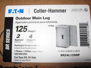
- Outdoor Main Lug Box - 125Amp, 2Spaces, 4Circuits, 1Phase, 3Wire, 120/240VAC
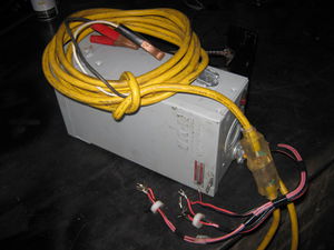
- Extension Cord
- Alligator clips (2)
- Home wiring box [1]
- Fuse holder - 30Amp Inline Mini Blade-Type Buy
- 12v quick connect plugs (5 pairs)
- Stranded 5A wire ?
- Spade terminals (10)
- Underground phone cable
- Potting compound Buy
- PVC pipe
- PVC pipe cap
- Stranded Cat 5 cable
- Supermagnets (6) - N42 Buy
- Arduino (Duemilanove) Buy
- MOSFET replacements (5) - Single 35A 70V 0.028Ω TO-220-3 Buy Buy
- Hall Effect sensors (2) - US1881 TO-92 Buy
- 3/8" V-groove bearings (4) Buy
- Molex connector Buy Buy Buy
Sub-project Materials
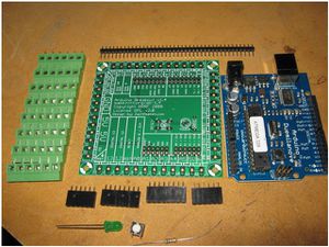
- Arduino breakout shield Buy Parts Assembly instructions
- PWM Solenoid drivers (2) Buy Parts Assembly instructions
Diagrams
- need a diagram of the wires
- google doc drawing of wire diagram (working on it)
Wiring Instructions
The CEB controller involves the following wiring:
- Battery power cord/Fuse/Switch
- Arduino/Breakout Board/Solenoid Driver sandwich
- Circuit board power – solenoid driver and Arduino power connections
- Sensor connections
- Solenoid driver power outputs to solenoids
- Solenoid connections
Note: Reversing the polarity on the power input to the solenoid driver has been shown to fry the solenoid driver board. Other damage may also occur by incorrect connection.
Battery Power
The Power Cube battery, or any other 12V source (Fig. 1), provides electrical power to drive the CEB controller (Fig. 2) and hydraulic solenoid valves (Fig. 3). Alligator clips (Fig. 4) are used to make the connection. The white lead in the power cord is the positive terminal, and the black lead is the negative terminal. This polarity matters.
The battery power cable connects to the controller via a safety disconnect (video in last year's CEB documentation) - which are 2 plugs plugged into each other (Fig. 5). Once battery power is connected, the main power switch (Fig. 6) turns on the power to the controller, where the controller feeds power to the solenoids. Inside the controller, a terminal strip (Fig. 7) is used for the ground (black) and positive connections to the circuit boards. A fuse (Fig. 8) should be located between the main power switch and the positive terminal.
Circuit Boards
Three circuit boards are used in the controller. They are plugged one on top of the next in a sandwich configuration. The spacer on the bottom is a standard household electrical outlet, which insulates the circuit boards from the controller box.
The bottom board is the Arduino (Fig. 9). The Arduino Breakout Board (Fig. 10) sits on top of the Arduino. The circuit-milled Solenoid Driver Board (Fig. 11) sits on top of the Breakout Board. The pins on each of the 3 boards line up (Fig. 12).
The circuit schematic of the Solenoid Driver Board is shown in Fig. 13, and the Bill of Materials in Fig. 14. This is care of Blair Evans of the Detroit Fab Lab.
Circuit Power
The Arduino and the Solenoid driver must be powered by 12V from the battery. For the Arduino, the connection is made via the Breakout Board. 12V from the battery must be connected to Vin on the shield (bottom right of Shield in Fig.10), and ground must be connected as well. Use the terminals above the Vin.
Power must be connected directly to the solenoid driver board via the terminals in the upper left of Fig. 15. The + terminal is 12V, and the – terminal is the battery ground.
Sensor Connections
The sensor connections are color coded: blue is the sensor input, blue/white is ground, and orange is 5V.
When looking at the Hall Effect Senor chip (now encapsulated) from the front (front is the side with the writing), the left pin is 5V (orange), the middle pin is ground (blue/white), and the right pin is the sensor input (blue). The pull-up resistor (10k on the Detroit Fab Lab solenoid driver board, already included on the driver board) is connected between the 5V and sensor input terminals.
To connect the sensors, use the terminals on the breakout board to make the connections. Use the Analog 0 (A0) and Analog 1 (A1) pins on the breakout board to connect to the main cylinder and secondary cylinder sensor inputs, respectively. Note: the 3rd sensor (soil shaker) is optional, and it will not be used here. Connect the sensor 5V connections to the corresponding terminals on the breakout board, and connect the grounds to the corresponding breakout board terminals as well. The sensor connections should look like that shown in Fig. 16.
Fabrication Steps
- Assemble entire Control Box
- Blue spacer box - Arduino attached on top with 2 small screws. Slightly slanted attachment to make screw holes fit on blue spacer box
- Terminal in electrical outlet box cut in half on metal cutoff saw to create + and - terminals
- Plastic mount on bottom of electrical box was shaved to allow 2 solenoid drivers to fit
Sensor Fabrication and Attachment
Fabricate the Sensors
- Cut three 3’ sections of Underground Telephone Cable.
- Strip about 3” of the outer covering off each end of the three sections
- Strip about ¼” off the orange, blue and blue-white wires at each end of each section.
- Tin the ends of the all of the wires on all of the sections
- Splice, with Solder, about 6” of the inner strands of some Cat-5 Cable (E17) to the wires at one end of each of the sections of Underground Telephone Cable
- Thread shrink-wrap (E28) to the three wires on the other end of each of the three sections of Underground Telephone Cable.
- Solder a Hall Effect Sensor (E20) to one endof the ther sections
- Pin 1: Orange
- Pin 2: Blue-White
- Pin 3: Blue
- Shrink the Shrink-Wrap around each of the solder joints
- Cut three 3” sections of PVC Pipe (E15).
- Place a section of Pipe around each of the three hall effect sensors and encase them in Potting Compound (E29) with the Pipe Caps (E16) in place.
Attach the Sensors
- Feed the CAT-5 ends of the sensor cables through either the power cable hole or the right side hole of the Electronics Box.
- Attach the orange ends of the sensor wires to GND terminals on the Breakout Shield.
- Attach the blue ends of the sensor wires to the 5V terminals on the Breakout Shield.
- Attach the blue-white ends of the sensor wires to terminals A0, A1 and A2 on the Breakout Shield.
Previous Testing Procedure
- Test Arduino on laptop - for example by blinking Channel 13 output on Duemilanove.
- Test sensors by passing magnets over them. See this sample code.
- Data Sheet
- Supply voltage is 5V from the Arduino breakout shield
- The pins are +,-, OUT reading from top (printed / smaller face)
- The output is "Open Drain" - this means you need a "pull up" resistor on the output (10K connected to +)
- This model is "latching" which means it turns on from one pole, and off by the other, remembering its state in the meantime.
Controller checklist (ie, So you don't burn your components, check these):
- Arduino powers on with USB cord? Check.
- Arduino works - ex. blink Channel 13 with an LED? Check. Atmega 328 Duemilanove - on Ubuntu 10.04.
- Controller main power switch light red when battery is connected and switch is turned on? Check.
- With Molex connectors disconnected, 12V appears at pins 1 and 2?
- With Molex connectors plugged into solenoid driver boards, main power switch turns the drivers on?
- Arduino powers on with battery supply after flipping main switch on?
- Solenoid drivers are turned on with main switch?
- Solenoids turn all of their MOSFETS as seen via indicator lights?
- Solenoids can cycle the solenoid valves?
C
- Test solenoid valves by attaching power to battery and running this sample code for 2 solenoid channels.
- Note we can reduce 3 solenoid channels to 2 by running both the shaker motor and the drawer cylinder from the same channel - the shaker is activated at every stroke of the drawer, as there is ample hydraulic fluid flow available in that part of the overall CEB operation cycle.
other pages with info that should end up on this page
![]() It has been suggested that the text on [[::CEB_Automation_Prototype_II|CEB_Automation_Prototype_II]] be merged into (added to) this page or section. (Discuss)
It has been suggested that the text on [[::CEB_Automation_Prototype_II|CEB_Automation_Prototype_II]] be merged into (added to) this page or section. (Discuss)
![]() It has been suggested that the text on [[::Arduino_Control_of_CEB_Prototype_2|Arduino_Control_of_CEB_Prototype_2]] be merged into (added to) this page or section. (Discuss)
It has been suggested that the text on [[::Arduino_Control_of_CEB_Prototype_2|Arduino_Control_of_CEB_Prototype_2]] be merged into (added to) this page or section. (Discuss)
![]() It has been suggested that the text on [[::FeF_Liberator_Fabrication|FeF_Liberator_Fabrication]] be merged into (added to) this page or section. (Discuss)
It has been suggested that the text on [[::FeF_Liberator_Fabrication|FeF_Liberator_Fabrication]] be merged into (added to) this page or section. (Discuss)


