CEB Press/Manufacturing Instructions/Controller Box/FeF Liberator Controller: Difference between revisions
Jump to navigation
Jump to search
(→Step 3) |
No edit summary |
||
| (31 intermediate revisions by 5 users not shown) | |||
| Line 1: | Line 1: | ||
=Step 2= | =Step 2= | ||
| Line 24: | Line 16: | ||
*Electronics Box - local hardware store | *Electronics Box - local hardware store | ||
*Extension Cord | *Extension Cord | ||
**Or house wiring with [http://www.harborfreight.com/125-volt-15-amp-female-plug-connector-93687.html Female Plug] and [http://www.harborfreight.com/125-volt-15-amp-male-plug-93686.html Male Plug]. | **Or house wiring with [http://www.harborfreight.com/125-volt-15-amp-female-plug-connector-93687.html Female Plug] and [http://www.harborfreight.com/125-volt-15-amp-male-plug-93686.html Male Plug]. | ||
*2 alligator clips for battery connection - auto parts store | *2 alligator clips for battery connection - auto parts store | ||
| Line 55: | Line 46: | ||
*<span style="color:green">[1] Arduino breakout shield - [http://store.makerbot.com/arduino-breakout-shield-v1-4-kit.html $25], Makerbot | *<span style="color:green">[1] Arduino breakout shield - [http://store.makerbot.com/arduino-breakout-shield-v1-4-kit.html $25], Makerbot | ||
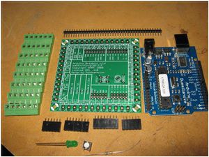
[[Image:Breakoutparts.jpg|thumb|Arduino breakout shield components. Solder green parts (left in picture) last, after the black pieces (bottom in picture).]] | |||
**Assembly instructions - [http://www.reprap.org/wiki/Arduino_Breakout_1_4] | |||
*<span style="color:green">[1] Arduino (Duemilanove) - [http://store.makerbot.com/arduino.html $30], Makerbot | *<span style="color:green">[1] Arduino (Duemilanove) - [http://store.makerbot.com/arduino.html $30], Makerbot | ||
*<span style="color:green">[2] Solenoid drivers -[http://store.makerbot.com/pwm-driver-v1-1-kit.html $13 ea.], Makerbot | *<span style="color:green">[2] Solenoid drivers -[http://store.makerbot.com/pwm-driver-v1-1-kit.html $13 ea.], Makerbot | ||
*<span style="color:green">[4] MOSFET replacements for solenoid drivers, VNP35N07-E - [http://www.futureelectronics.com/en/technologies/semiconductors/analog/drivers/mosfet-igbt-drivers/Pages/3890498-VNP35N07-E.aspx $3.34], Future Electronics (if not available, search at Octopart) (grate shaker is automated, no sensors needed for it) | **Assembly instructions - [http://www.reprap.org/wiki/PWM_Driver_1_1]. | ||
**total cost with shipping - $88.25 | |||
*<span style="color:green">[4] MOSFET replacements [http://forums.reprap.org/read.php?13,41238,41255,quote=1 (see discussion)] for solenoid drivers, VNP35N07-E - [http://www.futureelectronics.com/en/technologies/semiconductors/analog/drivers/mosfet-igbt-drivers/Pages/3890498-VNP35N07-E.aspx $3.34], Future Electronics (if not available, search at Octopart) (grate shaker is automated, no sensors needed for it) | |||
**Notes: The cheaper version recommended by Nophead from RepRap was this [http://octopart.com/partsearch/#search/requestData&q=VNP14NV04-E]. See [http://forums.reprap.org/read.php?13,41238,41255,quote=1 discussion]. | |||
**Total $25.70 (for 5) | |||
*<span style="color:green">[2] Hall Effect sensors - [http://www.sparkfun.com/commerce/product_info.php?products_id=9312 $0.95 ea], Sparkfun | *<span style="color:green">[2] Hall Effect sensors - [http://www.sparkfun.com/commerce/product_info.php?products_id=9312 $0.95 ea], Sparkfun | ||
**Total $9.16 (for 5) | |||
*<span style="color:green">[4] 3/8" V-groove bearings - [http://www.vxb.com/page/bearings/PROD/V-Groove-Bearings/Kit8405 $7.77 ea], VXB | *<span style="color:green">[4] 3/8" V-groove bearings - [http://www.vxb.com/page/bearings/PROD/V-Groove-Bearings/Kit8405 $7.77 ea], VXB | ||
**Total $42.47 | |||
*<span style="color:green">[6] Supermagnets - [http://www.gaussboys.com/ndfeb-magnets/D1203E-N42.html $0.48], Gaussboys | *<span style="color:green">[6] Supermagnets - [http://www.gaussboys.com/ndfeb-magnets/D1203E-N42.html $0.48], Gaussboys | ||
**Total $11.11 (for 12) | |||
Grand total for electronics, magnets, and bearings - $176.69 | |||
*<span style="color:green">[1] Potting Compound - [http://cgi.ebay.com/EPOXY-RESIN-CIRCUIT-BOARD-POTTING-COMPOUND-CASTING-48OZ-/310186942108?pt=LH_DefaultDomain_0&hash=item4838951e9c $22 for 48 oz], Polymer Composites | *<span style="color:green">[1] Potting Compound - [http://cgi.ebay.com/EPOXY-RESIN-CIRCUIT-BOARD-POTTING-COMPOUND-CASTING-48OZ-/310186942108?pt=LH_DefaultDomain_0&hash=item4838951e9c $22 for 48 oz], Polymer Composites | ||
* | *Molex connector for powering solenoid drivers - [http://www.radioshack.com/product/index.jsp?productId=2102783] | ||
*[1] Fuse holder - [http://www.radioshack.com/product/index.jsp?productId=2102783] | |||
* | |||
=Step 4= | =Step 4= | ||
Put together control box and test sensors | |||
*Assemble entire Control Box | |||
**Blue spacer box - Arduino attached on top with 2 small screws. Slightly slanted attachment to make screw holes fit on blue spacer box | |||
**Terminal in electrical outlet box cut in half on metal cutoff saw to create + and - terminals | |||
**Plastic mount on bottom of electrical box was shaved to allow 2 solenoid drivers to fit | |||
*Test Arduino on laptop - for example by [http://www.arduino.cc/en/Tutorial/Blink blinking Channel 13 output on Duemilanove]. | |||
*Test sensors by passing magnets over them. See this sample code. | |||
**[http://www.sparkfun.com/datasheets/Components/General/Hall-US1881EUA.pdf Data Sheet] | |||
**Supply voltage is 5V from the Arduino breakout shield | |||
**The pins are +,-, OUT reading from top (printed / smaller face) | |||
**The output is "Open Drain" - this means you need a "pull up" resistor on the output (10K connected to +) | |||
**This model is "latching" which means it turns on from one pole, and off by the other, remembering its state in the meantime. | |||
=Step 5= | |||
*Test solenoid valves by attaching power to battery and running this sample code for 2 solenoid channels. | |||
**Note we can reduce 3 solenoid channels to 2 by running both the shaker motor and the drawer cylinder from the same channel - the shaker is activated at every stroke of the drawer, as there is ample hydraulic fluid flow available in that part of the overall CEB operation cycle. | |||
=Step 6= | |||
Build sensor and magnet mounts, attach to the machine | |||
=Step 7= | |||
Mount control box and solenoid valve on the machine | |||
=Step 8= | |||
Test the entire machine | |||
*Test motion of main cylinder with this code | |||
*Test motion of soil drawer cylinder with this code. | |||
*Test motion of both cylinders, and machine is ready to run. | |||
[[Category:CEB Press Fabrication]] | |||
Latest revision as of 02:18, 27 August 2011
Step 2
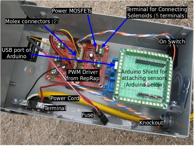
Source the electronics. Here is a diagram of the controller box
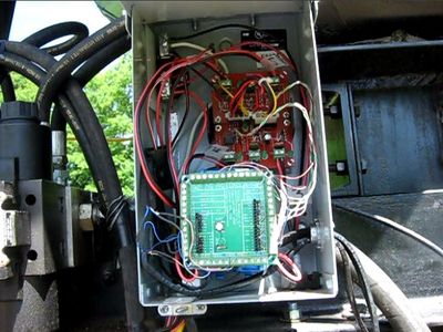
Here is the complete controller installed:
Gross Electronics:
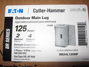
- Electronics Box - local hardware store
- Extension Cord
- Or house wiring with Female Plug and Male Plug.
- 2 alligator clips for battery connection - auto parts store
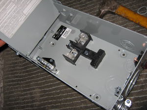
- House wiring box (blue box in picture above below the Arduino Shield - hardware store
- Fuse holder - car parts store
- 12v quick connect plugs - 5 pairs - for quick-coupling to solenoids out of controller box - car parts store
- Stranded 5A wire for solenoid connections
- Spade terminals (10) for connection to solenoid terminals
- Underground phone cable - makes very tough connectors for sensors
- Potting compound
- PVC pipe - with 1 end capped
- Stranded Cat 5 wire for sensor connections
- [5] Supermagnets -
Microelectronics:
- [2] Hall Effect Sensors - Sparkfun
- [1] Arduino shield kit - Makerbot
- [1] Arduino - Makerbot
- [2] RepRap PWM Driver Boards
Components for PWM Driver Boards
- [1] Replacement MOSFETS -
- []
Step 3
Shopping list for items which are shipped:
- [1] Arduino breakout shield - $25, Makerbot
- Assembly instructions - [1]
- [1] Arduino (Duemilanove) - $30, Makerbot
- [2] Solenoid drivers -$13 ea., Makerbot
- Assembly instructions - [2].
- total cost with shipping - $88.25
- [4] MOSFET replacements (see discussion) for solenoid drivers, VNP35N07-E - $3.34, Future Electronics (if not available, search at Octopart) (grate shaker is automated, no sensors needed for it)
- Notes: The cheaper version recommended by Nophead from RepRap was this [3]. See discussion.
- Total $25.70 (for 5)
- [2] Hall Effect sensors - $0.95 ea, Sparkfun
- Total $9.16 (for 5)
- [4] 3/8" V-groove bearings - $7.77 ea, VXB
- Total $42.47
- [6] Supermagnets - $0.48, Gaussboys
- Total $11.11 (for 12)
Grand total for electronics, magnets, and bearings - $176.69
- [1] Potting Compound - $22 for 48 oz, Polymer Composites
- Molex connector for powering solenoid drivers - [4]
- [1] Fuse holder - [5]
Step 4
Put together control box and test sensors
- Assemble entire Control Box
- Blue spacer box - Arduino attached on top with 2 small screws. Slightly slanted attachment to make screw holes fit on blue spacer box
- Terminal in electrical outlet box cut in half on metal cutoff saw to create + and - terminals
- Plastic mount on bottom of electrical box was shaved to allow 2 solenoid drivers to fit
- Test Arduino on laptop - for example by blinking Channel 13 output on Duemilanove.
- Test sensors by passing magnets over them. See this sample code.
- Data Sheet
- Supply voltage is 5V from the Arduino breakout shield
- The pins are +,-, OUT reading from top (printed / smaller face)
- The output is "Open Drain" - this means you need a "pull up" resistor on the output (10K connected to +)
- This model is "latching" which means it turns on from one pole, and off by the other, remembering its state in the meantime.
Step 5
- Test solenoid valves by attaching power to battery and running this sample code for 2 solenoid channels.
- Note we can reduce 3 solenoid channels to 2 by running both the shaker motor and the drawer cylinder from the same channel - the shaker is activated at every stroke of the drawer, as there is ample hydraulic fluid flow available in that part of the overall CEB operation cycle.
Step 6
Build sensor and magnet mounts, attach to the machine
Step 7
Mount control box and solenoid valve on the machine
Step 8
Test the entire machine
- Test motion of main cylinder with this code
- Test motion of soil drawer cylinder with this code.
- Test motion of both cylinders, and machine is ready to run.
