Cold Saw/V1 Design Files/Support Bar: Difference between revisions
< Cold Saw | V1 Design Files
Jump to navigation
Jump to search
| (6 intermediate revisions by the same user not shown) | |||
| Line 8: | Line 8: | ||
*''' | *'''Shaft Hole Diameter: 32mm''' | ||
*''' | *'''Shaft Hole Spacing Along Length: 260mm''' | ||
*''' | *'''Shaft Hole Spacing Along Width: 23.5mm''' | ||
*'''Shaft Hole Spacing: minimum of 40mm from part ends''' | |||
| Line 18: | Line 20: | ||
*'''Interface Hole Diameter: 12mm''' | *'''Interface Hole Diameter: 12mm''' | ||
*'''Interface Hole | *'''Interface Hole Rectangle: 75mm x 80mm''' | ||
*'''Stopper Hole Diameter: 12mm''' | *'''Stopper Hole Diameter: 12mm''' | ||
*'''Stopper Hole Spacing: | *'''Stopper Hole Spacing: 30mm x 45mm from Shaft Hole. (Such that the blade bottoms out just before touching the vise; such that the drive assembly can reliably and safely sit back without being held)''' | ||
Latest revision as of 23:31, 7 June 2012
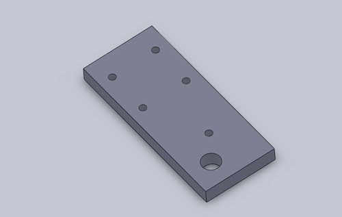
Support Bar
- Length: 300mm
- Width: 127mm
- Thickness: 25.4mm
- Shaft Hole Diameter: 32mm
- Shaft Hole Spacing Along Length: 260mm
- Shaft Hole Spacing Along Width: 23.5mm
- Shaft Hole Spacing: minimum of 40mm from part ends
- Interface Hole Diameter: 12mm
- Interface Hole Rectangle: 75mm x 80mm
- Stopper Hole Diameter: 12mm
- Stopper Hole Spacing: 30mm x 45mm from Shaft Hole. (Such that the blade bottoms out just before touching the vise; such that the drive assembly can reliably and safely sit back without being held)
- Stopper Notes: Remember that the stopper screw will have a nut on it which determines the contact diameter of the stopper.
- 2D Image
- 3D CAD STP
- 2D Fabrication Drawing PDF
- 2D Fabrication Drawing DXF
