TorchTableToolChainTesting: Difference between revisions
| Line 64: | Line 64: | ||
The below is adapted from http://www.cnczone.com/forums/alibre_design/157372-alibre_dxf.html (re: Need Help!- Alibre to dxf? ) | The below is adapted from http://www.cnczone.com/forums/alibre_design/157372-alibre_dxf.html (re: Need Help!- Alibre to dxf? ) | ||
[[File:Alibre_part.png|thumb|Make part]] [[File:Alibre_pop-ups.png|thumb|importing part to drawing]] [[File:Alibre_export.png|thumb|Export dxf]] | |||
* Open Alibre to make a new Part. | * Open Alibre to make a new Part. | ||
* Make a 2D sketch in part modeling | * Make a 2D sketch in part modeling | ||
Revision as of 20:13, 8 December 2012
Tool chain experiments for Torch Table programming
Initial tests ChuckH 22:52, 2 December 2012 (CET)
- environment: Windows XP SP3 laptop
- software installation
- inkscape download inkscape 0.48.2, standard Windows exe installer to Program Files/Inkscape
- gcodetools download gcodetools v1.7 here and unpack into Inkscape subdirectory per instructions.
- implicitCAD
- Haskell Platform download installer here. Some Haskell packages are not too happy with Windows path name conventions, particularly spaces inside filenames. I installed at C:\Haskell_Platform instead of the default C:\Program Files\Haskell_Platform. However, this may not be necessary.
- download implicitCAD using cabal (see [instructions]), but it does not build properly. (Unfortunately I did not record exactly my sequence of steps here. Among other things I think I needed to copy mingw's gawk program and rename it awk for cabal to build.)
- patch implicitCAD files to enable Windows install. File:ImplicitCADWindowsPatch0.docThis patch made it compile for me, at the cost of disabling PNG output (not necessary for our toolchain) and disabling file includes (probably painful; need workaround).
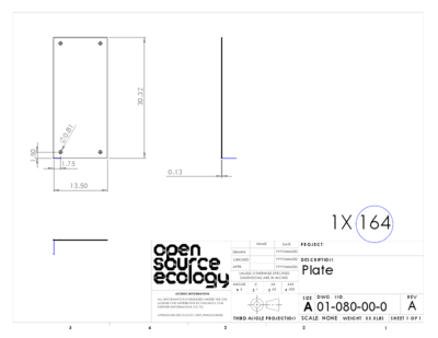
simple test part
/* 164_plate.escad, units=inch */
p164_wd = 13.5;
p164_ln = 30.32;
holedia = 0.81;
inset_x = 1.75;
inset_y = 1.5;
difference() {
  square([p164_wd, p164_ln]);
  union() {
    translate([inset_x, inset_y]) circle(holedia/2);
    translate([p164_wd-inset_x, inset_y]) circle(holedia/2);
    translate([inset_x, p164_ln-inset_y]) circle(holedia/2);
    translate([p164_wd-inset_x, p164_ln-inset_y]) circle(holedia/2);
  }
}
run implicitCAD's extopenscad program
extopenscad 164_plate.escad out.svg
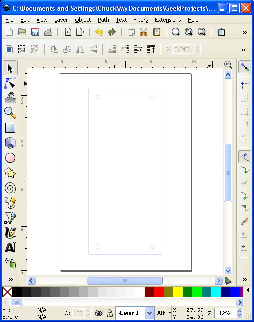
Unfortunately, the out.svg file does not contain any clues that the units are inches, and if we open this file with inkscape it will assume user units are pixels. Based on this posting I found that user units can be forced to inches by substituting a few lines near the beginning of the svg file. Here is a diff
4c4,9
< <svg xmlns="http://www.w3.org/2000/svg" xmlns:xlink="http://www.w3.org/1999/xlink" version="1.1"><g stroke="rgb(0,0,255)" stroke-width="1" fill="none">
---
> <svg xmlns="http://www.w3.org/2000/svg" xmlns:xlink="http://www.w3.org/1999/xlink" version="1.1"
>    width="100in"
>    height="100in"
>    viewBox="0 0 100 100"
> >
> <g stroke="rgb(0,0,255)" stroke-width="0.01" fill="none">
Full file at [1].
Inkscape svg to gcode
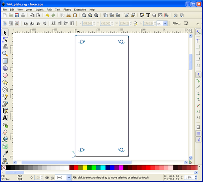
It is apparent that implicitCAD generates lots of short straight line segments, subdividing longer lines and approximating the pure circles. This can confuse the plasma lead-in generator in gcodetools:
Alibre -> DXF toolchain
OSE_Christmas_Gift_to_the_World_2012#Hopper_CAD_drawings
Verified in Alibre v12.
The below is adapted from http://www.cnczone.com/forums/alibre_design/157372-alibre_dxf.html (re: Need Help!- Alibre to dxf? )
- Open Alibre to make a new Part.
- Make a 2D sketch in part modeling
- Now give the part some thickness "Extrude Boss" say maybe .125 inches
- Now save as: The name you give it. say "TestPartOne"
- Close out of "Part Modeling"
- Now in Alibre create a new drawing
- File - New - Drawing
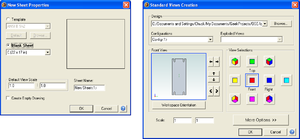
- A window should pop up that says "New Sheet Properties"
- Check - Blank Sheet - Custom 8.5 by 11 is OK - set default scale view at 1 to 1 - enter sheet name say " TestPartOneDrawing" click OK
- Click on "Test Part One"
- A window should pop up "Standard Views Creation"
- View selections - click on "Front" and uncheck all other views
- Set scale at - 1:1 click OK
- Now click on the open work space and your drawing should appear
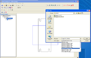
- Drop down menu click "Export"
- Give it a file name say "TestPartOne_CAM"
- Save as type - drop down menu on the right hand side "AutoCAD 2000 file dxf"
- Click "Save"
- Close all your Alibre files
Note that using 1:1 scale the part probably doesn't fit on the sheet. That's okay, what's important is that the numbers that go into the dxf file are un-scaled inches.
