TorchTableToolChainTesting
Main > Digital Fabrication > RepLab Tools > Torch Table
Tool chain experiments for Torch Table programming
Initial tests ChuckH 22:52, 2 December 2012 (CET)
- environment: Windows XP SP3 laptop
- software installation
- inkscape download inkscape 0.48.2, standard Windows exe installer to Program Files/Inkscape
- gcodetools download gcodetools v1.7 here and unpack into Inkscape subdirectory per instructions.
- implicitCAD
- Haskell Platform download installer here. Some Haskell packages are not too happy with Windows path name conventions, particularly spaces inside filenames. I installed at C:\Haskell_Platform instead of the default C:\Program Files\Haskell_Platform. However, this may not be necessary.
- download implicitCAD using cabal (see [instructions]), but it does not build properly. (Unfortunately I did not record exactly my sequence of steps here. Among other things I think I needed to copy mingw's gawk program and rename it awk for cabal to build.)
- patch implicitCAD files to enable Windows install. File:ImplicitCADWindowsPatch0.docThis patch made it compile for me, at the cost of disabling PNG output (not necessary for our toolchain) and disabling file includes (probably painful; need workaround).
implicitCAD hierarchical design
I have been using gnu make and cpp (c macro preprocessor) with extopenSCAD files to manage dependencies.
Work in progress on github.
// cpp test part
// gantry drive side rail
#include "StepperMounts/size34.escad"
#include "HardwareMounts/FlangedBush375.escad"
mmPerIn = 25.4;
center_dist = 18;
lip_width = 2;
plate_length = center_dist+4;
plate_width = lip_width+4;
difference() {
  unit("in") {
    square([plate_length,plate_width]);
  }
  union() {
    translate([2*mmPerIn, 4*mmPerIn]) size34_cutout(); // motor mount
    translate([(2+center_dist)*mmPerIn, 4*mmPerIn]) SDPA7Z63FDU375_adjustable(0.375); // idler pulley mount
    foldline([0,lip_width]*mmPerIn, [plate_length, lip_width]*mmPerIn); // L-fold
    foldUpTab([4,lip_width+1.5]*mmPerIn, [8,lip_width+1.5]*mmPerIn, -0.75*mmPerIn); // home sensor flag
    foldUpTab([4,lip_width+2.25]*mmPerIn, [6,lip_width+2.25]*mmPerIn, 0.75*mmPerIn); // limit sensor flag 1
    foldUpTab([center_dist-2,lip_width+2.25]*mmPerIn, [center_dist,lip_width+2.25]*mmPerIn, 0.75*mmPerIn); // limit sensor flag 2
  }
}

$quality = 20;
Bends and tabs
Sheet-metal bends and fold-up tabs are useful features. When designing these it is necessary to make bend allowance. I am hoping to incorporate bend allowance computation into the extopenSCAD toolchain.
simple test part
implicitCAD
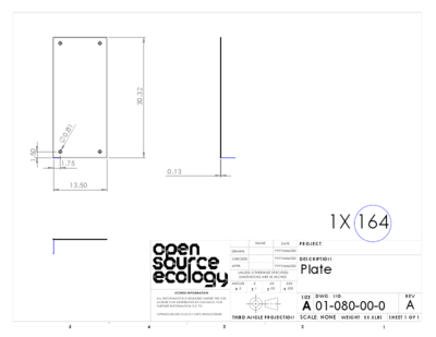
/* 164_plate.escad, units=inch */
unit("in") {
  p164_wd = 13.5;
  p164_ln = 30.32;
  holedia = 0.81;
  inset_x = 1.75;
  inset_y = 1.5;
  difference() {
    square([p164_wd, p164_ln]);
    union() {
      translate([inset_x, inset_y]) circle(holedia/2);
      translate([p164_wd-inset_x, inset_y]) circle(holedia/2);
      translate([inset_x, p164_ln-inset_y]) circle(holedia/2);
      translate([p164_wd-inset_x, p164_ln-inset_y]) circle(holedia/2);
    }
  }
}
run implicitCAD's extopenscad program
extopenscad 164_plate.escad out.svg
Hmmm. This used to work but now it doesn't like the output file being specified
>extopenscad 164_plate.escad out.svg
Rendering 3D object to out.svg
With resolution 17.129469
extopenscad: Prelude.head: empty list
With no output filename specified, it renders to <sourcefilename>.svg ok. ChuckH 12:29, 14 December 2012 (CET)
inkscape
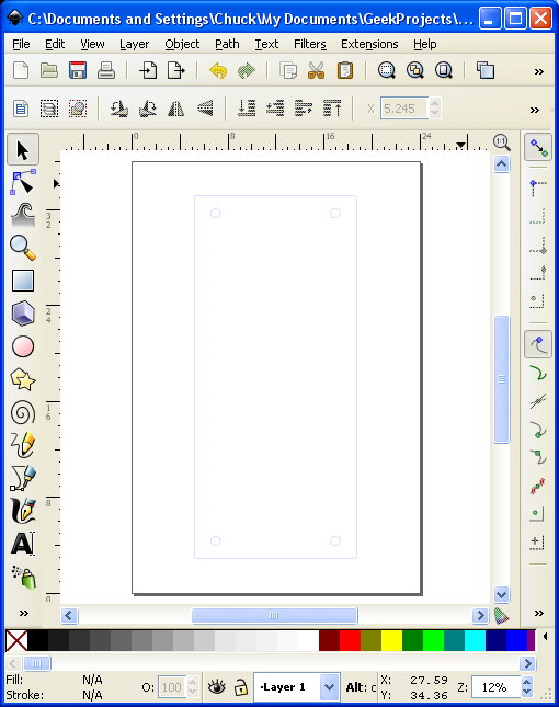
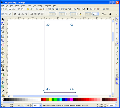
I haven't figured out how Inkscape decides where to place the obect on the sheet when it is opened or imported. But at least it's the right size.
Full file at [1].
Inkscape svg to gcode
- Open part.svg file.
If object is on "root" layer, try this:
1) Create a new layer.
2) Edit --> XML editor
3) Look for the the layer object. Use the buttons at the top of the window to move it near the top of the list, just under the metadata and above all of the actual objects in the drawing.
4) Select each of the objects one by one, starting from the top, and click the "indent node" button to move them to be children of the layer.
- gcodetools orientation points
- 2 points rotate mode
- Z surface = 0
- Z depth = -0.5 in (?)
- Apply - creates two labelled points near the bottom of image
- gcodetools Tools Library
- plasma
- Apply - creates a table of tool parameters as an object embedded in the image
- edit the tool parameter table
- diameter = 0.1
- feed = 100 (ipm?)
- penetration feed = 50 ?
- piercing gcode
G31 Z-1 F500 (find metal)
G92 Z0 (zero z)
G00 Z0.25 F500 (going up)
M03 (turn on plasma)
G04 P0.2 (pause)
G01 Z0.13 (going to cutting z)
- inkscape Path - object to path
- gcodetools Prepare path for plasma
- create in-out paths
- gcodetools Path to Gcode
- Preferences tab
- Directory C:\Documents and Settings\Chuck\My Documents (default is C:\Program Files\Inkscape\share\extensions)
- Z safe height 1 in
- Path to Gcode tab, Apply
- Preferences tab
(Header)
(Generated by gcodetools from Inkscape.)
(Using default header. To add your own header create file "header" in the output dir.)
M3
(Header end.)
G20 (All units in inches)

(Start cutting path id: polyline3363)
(Change tool to Plasma cutter)

G00 Z1.000000
G00 X3.276600 Y29.789413
G31 Z-1 F500 (find metal)
G92 Z0 (zero z)
G00 Z0.25 F500 (going up)
M03 (turn on plasma)
G04 P0.2 (pause)
G01 Z0.13 (going to cutting z)
G01 Z-0.500000 F50.0(Penetrate)
G01 X3.240275 Y29.811148 Z-0.500000 F100.000000
G01 X3.214352 Y29.844613 Z-0.500000
G01 X3.201958 Y29.890871 Z-0.500000
G01 X3.209604 Y29.938146 Z-0.500000
G01 X3.235972 Y29.978166 Z-0.500000
G01 X3.276600 Y30.003588 Z-0.500000
G01 X3.344040 Y30.007502 Z-0.500000
G01 X3.401744 Y29.972378 Z-0.500000
G01 X3.429495 Y29.911109 Z-0.500000
G01 X3.419384 Y29.844613 Z-0.500000
G01 X3.393352 Y29.812415 Z-0.500000
G01 X3.358270 Y29.790425 Z-0.500000
G01 X3.317529 Y29.782375 Z-0.500000
G01 X3.276600 Y29.789413 Z-0.500000
G00 Z1.000000
M05 (turn off plasma)
(End cutting path id: polyline3363)


(Start cutting path id: polyline3361)
(Change tool to Plasma cutter)

G00 Z1.000000
G00 X0.533400 Y29.789413
G31 Z-1 F500 (find metal)
G92 Z0 (zero z)
G00 Z0.25 F500 (going up)
M03 (turn on plasma)
G04 P0.2 (pause)
G01 Z0.13 (going to cutting z)
G01 Z-0.500000 F50.0(Penetrate)
G01 X0.492471 Y29.782375 Z-0.500000 F100.000000
G01 X0.451730 Y29.790426 Z-0.500000
G01 X0.416647 Y29.812415 Z-0.500000
G01 X0.390616 Y29.844613 Z-0.500000
[...]
G01 X3.393352 Y29.812415 Z-0.500000
G01 X3.358270 Y29.790425 Z-0.500000
G01 X3.317529 Y29.782375 Z-0.500000
G01 X3.276600 Y29.789413 Z-0.500000
G02 X3.151337 Y29.865400 Z-0.500000 I0.033891 J0.197108
G02 X3.111479 Y30.006383 Z-0.500000 I0.159154 J0.121120
G00 Z1.000000
M05 (turn off plasma)
(End cutting path id: path4121)


(Footer)
M5
G00 X0.0000 Y0.0000
M2
(Using default footer. To add your own footer create file "footer" in the output dir.)
(end)
%
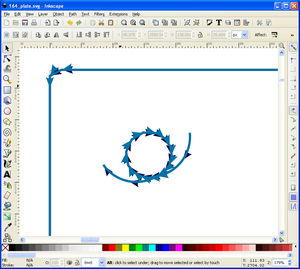
It looks as if gcodetools treated the holes as male, and didn't offset by the tool diameter.
Open issues
open paths
Many parts require the torch to simply cut along line (not a closed path), for example narrow slots for fold lines. There doesn't seem to be any way to generate an open path with implicitCAD. Maybe gcodetools can identify narrow (<= kerf-width) slots and convert them to open paths. Alternatively a purpose-built Python script using the xtree package (parses xml; svg is an xml format) could identify narrow paths.
Alibre -> DXF toolchain
OSE_Christmas_Gift_to_the_World_2012#Hopper_CAD_drawings
Verified in Alibre v12.
The below is adapted from http://www.cnczone.com/forums/alibre_design/157372-alibre_dxf.html (re: Need Help!- Alibre to dxf? )
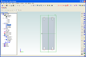
- Open Alibre to make a new Part.
- Make a 2D sketch in part modeling
- Now give the part some thickness "Extrude Boss", say maybe .125 inches
- Now save as: The name you give it. say, "TestPartOne"
- Close out of "Part Modeling"
- Now in Alibre create a new drawing
- File - New - Drawing
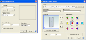
- A window should pop up that says "New Sheet Properties"
- Check - Blank Sheet - Custom 8.5 by 11 is OK - set default scale view at 1 to 1 - enter sheet name, say "TestPartOneDrawing" click OK
- Click on "TestPartOne"
- A window should pop up "Standard Views Creation"
- View selections - click on "Front" and uncheck all other views
- Set scale at - 1:1 click OK
- Now click on the open work space and your drawing should appear
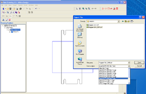
- Drop down menu click "Export"
- Give it a file name, say "TestPartOne_CAM"
- Save as type - drop down menu on the right hand side "AutoCAD 2000 file dxf"
- Click "Save"
- Close all your Alibre files
Note that using 1:1 scale the part probably doesn't fit on the sheet. That's okay, what's important is that the numbers that go into the dxf file are un-scaled inches.
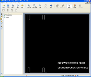
Verified that dxf file exported from Alibre will import into Torchmate CNC software.
Alternate path Alibre->pdf->inkscape
- Print scale drawing (e.g. 1:4 scale) from Alibre using PDFCreator.
- Note: although both Alibre and PDFCreator allow custom sheet sizes large enough to accommodate a 1:1 part, I get an incorrect pdf (e.g. printing Hopper_151_CAM.AD_PRT on an 80-inch x 20-inch sheet)
- Open pdf file with inkscape
- Use inkscape Transform - Scale to restore to full scale
- Ungroup drawing in inkscape
- Select and delete undesired parts of image
- Group the part geometry elements
So far it is not clear whether or not the resulting path is good for gcodetools. To be continued.
DXF to Inkscape
Inkscape can open a dxf file. However, as of version 0.48, there is only partial support for dxf features; for example Inkscape does not handle dimensions, text formatting or line types very well, and it assumes the dxf file units are mm. Nonetheless, we can successfully import the important elements of part geometry in order to create a tool path.
- Start Inkscape
- Open the dxf file
- use File Open rather than File Import .. this will bring in dxf layers as Inkscape layers
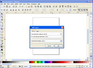
- on the DXF input pop-up, uncheck "Use automatic scaling to size A4" and set the manual scale factor to 25.4 (mm per inch)
- Clean up to taste
- Make the object lines into a group (select them, then menu Object Group) so they will stay together
- Choose an appropriate page size (menu File DocumentProperties)
- Move the object to a more convenient place on the sheet
- Select any unnecessary parts of the drawing (text, title block, etc.) and delete them
- Save file

