Talk:CEB Press v16.09/SCAD Files: Difference between revisions
Jump to navigation
Jump to search
No edit summary |
|||
| (6 intermediate revisions by the same user not shown) | |||
| Line 17: | Line 17: | ||
===Frame=== | ===Frame=== | ||
suggest adding new diagnal support part that welds between F5 and F4 to guarantee 90 degree weld and prevent bending under loads | suggest adding new diagnal support part that welds between F5 and F4 to guarantee 90 degree weld and prevent bending under loads --[[User:Dorkmo|Dorkmo]] ([[User talk:Dorkmo|talk]]) 03:50, 31 May 2017 (CEST) | ||
=Design Method= | |||
==Module Insert== | |||
a whole cut to allow for a matching tab to be placed within it and welded | |||
due to the varriance in styles this needs to be a flexiible module | |||
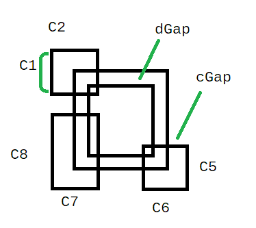
variables will be the height and width of the tab to be inserted, the gap to be left between the tab and the insert's wall, and 2 measurements for each corner cut, and the depth of the corner cut from the rest of the cut. | |||
[[image:ceb_scadinsertdiagram.png]] | |||
<nowiki> | |||
insert(2,1,0.5,0.125,0.125,0.125,0.125,0.25,0.25,0.125,0.125,0.25,0.25,1); | |||
module insert(X,Y,Z,dGap,cGap,c1,c2,c3,c4,c5,c6,c7,c8,center){ | |||
translate([-dGap-(center*(X/2)),-dGap-(center*(Y/2)),0]){ | |||
//main cut | |||
cube([X+(dGap*2),Y+(dGap*2),Z]); | |||
//corner c1c2 | |||
translate([-cGap,(Y+(dGap*2))-c1+cGap,0]) | |||
{ | |||
cube([c2,c1,Z]);} | |||
//corner c3c4 | |||
translate([(X+(dGap*2))-c3+cGap,(Y+(dGap*2))-c4+cGap,0]){ | |||
cube([c3,c4,Z]); | |||
} | |||
//corner c5c6 | |||
translate([(X+(dGap*2))-c6+cGap,-cGap,0]) | |||
{ | |||
cube([c6,c5,Z]); | |||
} | |||
//corner c7c8 | |||
translate([-cGap,-cGap,0]){ | |||
cube([c7,c8,Z]); | |||
} | |||
} //end center translate | |||
} | |||
</nowiki> | |||
Latest revision as of 02:17, 2 June 2017
TO DO
- do a full assembly
- notate which adjoining part corresponds with each cutout
- begin making design parametric - start a new "SCAD Files - Parametric" page
- Frame length and mounting hole dimensions based on cylinder
- set size of brick, drawer parts change to fit
- fix bugs in design
- standardize sizes where possible
- Layout for CNC
Design Suggestions
Frame
suggest adding new diagnal support part that welds between F5 and F4 to guarantee 90 degree weld and prevent bending under loads --Dorkmo (talk) 03:50, 31 May 2017 (CEST)
Design Method
Module Insert
a whole cut to allow for a matching tab to be placed within it and welded
due to the varriance in styles this needs to be a flexiible module
variables will be the height and width of the tab to be inserted, the gap to be left between the tab and the insert's wall, and 2 measurements for each corner cut, and the depth of the corner cut from the rest of the cut.
insert(2,1,0.5,0.125,0.125,0.125,0.125,0.25,0.25,0.125,0.125,0.25,0.25,1);

module insert(X,Y,Z,dGap,cGap,c1,c2,c3,c4,c5,c6,c7,c8,center){
    translate([-dGap-(center*(X/2)),-dGap-(center*(Y/2)),0]){
        //main cut
        cube([X+(dGap*2),Y+(dGap*2),Z]);
        //corner c1c2
        translate([-cGap,(Y+(dGap*2))-c1+cGap,0])
            {
        cube([c2,c1,Z]);}
       //corner c3c4
       translate([(X+(dGap*2))-c3+cGap,(Y+(dGap*2))-c4+cGap,0]){
           cube([c3,c4,Z]);
       }
       //corner c5c6
       translate([(X+(dGap*2))-c6+cGap,-cGap,0])
      {
          cube([c6,c5,Z]);
      }

       //corner c7c8
       translate([-cGap,-cGap,0]){
           cube([c7,c8,Z]);
       }

    } //end center translate
}
