|
|
| (11 intermediate revisions by the same user not shown) |
| Line 1: |
Line 1: |
| THIS INSTRUCTION IS NOT COMPLETED AND NOT READY FOR USE.
| | The selection of motor includes the following steps (which are described in further detail on this page): |
|
| |
|
| The selection of motor includes the following steps (which are described in further detail on this page):
| | * Step 1) Prerequisite: select Drive Mechanism |
|
| |
|
| * Step 1) Understand the prerequisites
| |
| * Step 2) Select motor type | | * Step 2) Select motor type |
| * Step 2) ...
| | |
| * Step 2) ... | | * Step 3) Dimension the motor |
|
| |
|
| =Step 1) Prerequisites= | | =Step 1) Prerequisites= |
| Line 12: |
Line 11: |
|
| |
|
| ==Prerequisite 1) Select Driven Mechanism == | | ==Prerequisite 1) Select Driven Mechanism == |
| Before selecting a motor, select the Driven Mechanism which can perform the intended output motion when connected to and driven by the motor. | | Before selecting a motor, select the Drive mechanism which can perform the intended output motion when connected to and driven by the motor. See the following guide for a comparison between different drive mechanisms: |
|
| |
|
| {| class="wikitable"
| | [[Drive mechanism selection]] |
| ! Application factors !! Belt drives !! Chain drives !! Rack/Gear and pinion !! Roller Pinon/rack !! Leadscrews !! Ballscrews !! Linear Motors
| |
| |-
| |
| | '''Accuracy''' || Low || Low || Low-High || High || Low || Low-High || High
| |
| |-
| |
| | '''Backlash/Vibration''' || A consideration || A consideration || A consideration || Near Zero || A consideration || A consideration || Near Zero
| |
| |-
| |
| | '''Acceleration''' || Medium || Low || High || High || Low || Medium || High
| |
| |-
| |
| | '''Speed''' || Medium || Low || Medium || High || Low || Medium || High
| |
| |-
| |
| | '''Load capacity''' || Low || Medium || High || High || Low || High || Low
| |
| |-
| |
| | '''Length''' || Shorter || Shorter || Long || Long || Shorter || Shorter || Moderate
| |
| |-
| |
| | '''High wear and short life''' || A consideration || A consideration || A consideration || Long life || A consideration || A consideration || Long life
| |
| |-
| |
| | '''Maintenance''' || A consideration || A consideration || A consideration || Low to none || A consideration || A consideration || Low to none
| |
| |-
| |
| | '''Noise level''' || Medium || High || Medium || Low || High || Medium || Low
| |
| |-
| |
| | '''Dust and dirt emissions''' || High || High || Moderate || Low to none || Moderate || Moderate || Low to none
| |
| |}
| |
|
| |
|
| ==Prerequisite 2) Identify the available power supply== | | ==Prerequisite 2) Identify the available power supply== |
| Line 47: |
Line 24: |
|
| |
|
| =Step 2) Select the motor type= | | =Step 2) Select the motor type= |
| | In summary |
| | *Servo motors are suitable for high speed and high acceleration requirements. The trade-off is a higher cost and complexity. |
| | *Stepper motors are suitable for low speed and low acceleration requirements. |
| | *DC motors are suitable for continuous rotation at high RPMs and constant torque across the motor’s speed range. |
|
| |
|
| ==Step 2.1) Identify application and desired motor attributes== | | ==Step 2.1) Identify application and desired motor attributes== |
| Line 231: |
Line 212: |
| |} | | |} |
|
| |
|
| =Step 4) Dimension the motor= | | =Step 3) Dimension the motor= |
| Now that we have selected the motor type, the motor has to be dimensioned. That means we need to conclude how powerful the motor must be in order to perform the intended task. If the motor is under-dimensioned, it won't be powerful enough to perform the intended task. If the motor is over-dimensioned, it's price and operation cost will be too high.
| | Once the motor type has been selected, the motor has to be "dimensioned" or "sized." This means that we need to select a motor that is of the right size and power. |
| | |
| These are the sub-steps for dimensioning the motor:
| |
| | |
| * Step 4.1) Load calculation
| |
| * Step 4.2) Mechanism calculation
| |
| * Step 4.3) Transmission calculation
| |
| | |
| Dimensioning the motor can either be done manually or by using a Motor Dimensioning Software (also referred to as motor selection software.)
| |
| | |
| ==Step 4.1) Load calculation==
| |
| The Load is constituted by
| |
| * The Mass of the object that the motor is intended to move (this does not include the mechanism which is covered in the next step.)
| |
| * External Forces that will require more work to be performed by the motor.
| |
| | |
| | |
| Note the Mass of the object that motor is intended to move.
| |
| | |
| Note any External Forces that will require more work to be performed by the motor.
| |
| | |
| ==Step 4.2) Drive mechanism calculation==
| |
| The motor must not only be strong enough to move the Load - it must be strong enough to move the Mechanism the the Load is applied to. For example, if the application is a belt conveyor intended to move boxes from one end to another, the motor will have to be strong enough to move the boxes that together make up the Load (covered in the step above), plus the Mechanism which includes the belt as well as the wheel that drives the belt.
| |
| | |
| Depending on the type of Drive mechanism, there are usually two parameters of interest:
| |
| * the Mass of the mechanism and
| |
| * the Moment of Intertia of the mechanism
| |
| | |
| Moment of Inertia is a measurement of how much effort is required to rotate an object. The Moment of Inertia for an object is determined by:
| |
| | |
| * The rotational axis relative to the object
| |
| * The shape and size of the object
| |
| * The mass of the object
| |
| | |
| Jump to the sub-chapter corresponding to the selected drive according to the list below:
| |
| {| class="wikitable" style="vertical-align:bottom;"
| |
| |- style="font-weight:bold;"
| |
| ! Mechanism
| |
| ! Jump to step
| |
| |-
| |
| | Belt Drive
| |
| | Step) 4.2.1
| |
| |-
| |
| | Ball Screw
| |
| | Step) 4.2.2
| |
| |-
| |
| | Chain and Sprocket
| |
| | Step) 4.2.3
| |
| |-
| |
| | Rack and Pinion
| |
| | Step) 4.2.4
| |
| |-
| |
| | Linear Motor
| |
| | Step) 4.2.5
| |
| |-
| |
| | Roll Feeder
| |
| | Step) 4.2.6
| |
| |-
| |
| | Rotational Table
| |
| | Step) 4.2.7
| |
| |-
| |
| | Crank
| |
| | Step) 4.2.8
| |
| |}
| |
| | |
| ===Step) 4.2.1 Belt Drive===
| |
| In a Belt Drive the motor is coupled to a timing pulley that drives a flexible toothed belt, with its coupled load, back and forth between two idler pulley guides.
| |
| | |
| ====Step) 4.2.1.1 Note pitch diameter====
| |
| | |
| The Driver Pitch Diameter is slightly larger than the outer diameter of the pulley and corresponds to the pitch line of the belt which is the line formed by the belt’s tensile cord.
| |
| | |
| [[File:Pitch diameter, belt drive.png|300px]]
| |
| | |
| The Pitch Diameter value can be used to calculate a rotational to linear ratio as given by:
| |
| | |
| V = ω * (D / 2)
| |
| | |
| where
| |
| | |
| V = rotational to linear ratio
| |
| | |
| D = Pitch Diameter
| |
| | |
| ω = the angular speed measured in radians per second
| |
| | |
| ====Step) 4.2.1.2 Note Belt Mass====
| |
| Belt Mass is the mass of the belt including any objects that are moving the load linearly. The Load (calculated in Step 4.1) is excluded from belt mass.
| |
| | |
| ====Step) 4.2.1.3 Note Driver/Idler Inertia====
| |
| Driver/Idler Inertia is the inertia of the mechanism that moves the load. This includes any rotationally moving parts that are not a part of the motor or transmission.
| |
| | |
| ====Step) 4.2.1.4 Note Efficiency====
| |
| Mechanical efficiency is measured as the ratio of the measured performance to the performance of an ideal machine. It is entered as a value between 0 and 1. See chapter "List of typical mechanical efficiencies" in this article.
| |
| | |
| ===Step) 4.2.2 Ball Screw===
| |
| A ball screw is coupled to a rotary motor and causes linear motion between a rotating screw and its non-rotating nut.
| |
| | |
| ====Step) 4.2.2.1 Note Lead====
| |
| The Lead is a measurement of the distance that the Load will move linearly with a single full revolution of the screw. The Lead for different ball screws can be found in product catalogs and are normally specified in millimeters.
| |
| | |
| ====Step) 4.2.2.2 Note Slide Mass====
| |
| Slide Mass is the mass of the slide including any objects that are moving the load linearly. The Load (calculated in previous steps) is excluded from this mass.
| |
| | |
| ====Step) 4.2.2.3 Note Ball Screw Inertia====
| |
| A Ball Screw has a cylindrical shape and will rotate around its central axis and can therefore be calculated like this:
| |
| | |
| I = 1/2 * m * r^2
| |
| | |
| where
| |
| | |
| I = Moment of Inertia
| |
| | |
| m = Mass
| |
| | |
| r = Radius
| |
| | |
| For a graphical explanation, see figure C in the chapter "''Table of equations for Moment of Inertia for different shapes''" in this article.
| |
| | |
| | |
| If the mass is not known, the following formula can be used:
| |
| | |
| I = (π/32) * D^4*ρ*L
| |
| | |
| where
| |
| | |
| I = Moment of Inertia
| |
| | |
| ρ = Density for the material that the Ball Screw is made from
| |
| | |
| L = Length
| |
| | |
| ====Step) 4.2.2.4 Note Coupling Inertia====
| |
| If Couplings are attached to the Ball Screw, their Moment of Inertia must be factored in the same way as for the Ball Screw covered in the step above.
| |
| | |
| ====Step) 4.2.2.5 Note Efficiency====
| |
| Mechanical efficiency is measured as the ratio of the measured performance to the performance of an ideal machine. It is entered as a value between 0 and 1. See chapter "List of typical mechanical efficiencies" in this article.
| |
| | |
| ===Step) 4.2.3 Chain and Sprocket===
| |
| A chain and sprocket is a rotary motor coupled to a sprocket wheel that drives a linked chain, with its coupled load, back and forth between idler sprocket guides.
| |
| | |
| ====Step) 4.2.3.1 Note Sprocket Pitch Circle Diameter====
| |
| Sprocket Pitch Circle Diameter is a measure of the diameter that the chain moves about. This value is used to calculate a rotational to linear ratio as given by:
| |
| | |
| V = ω * (D / 2)
| |
| | |
| where
| |
| | |
| V = rotational to linear ratio
| |
| | |
| D = Pitch Diameter
| |
| | |
| ω = the angular speed measured in radians per second
| |
| | |
| ====Step) 4.2.3.2 Note Chain Mass====
| |
| Chain Mass is the mass of the chain including any objects that are moving the load linearly. The Load (calculated in previous steps) is excluded from this mass.
| |
| | |
| ====Step) 4.2.3.3 Note Sprocket/Idler Inertia====
| |
| Sprocket/Idler Inertia is the inertia of the mechanism that moves the load. This includes any rotationally moving parts that are not a part of the motor or transmission.
| |
| | |
| ====Step) 4.2.3.4 Note Efficiency====
| |
| Mechanical efficiency is measured as the ratio of the measured performance to the performance of an ideal machine. It is entered as a value between 0 and 1. See chapter "List of typical mechanical efficiencies" in this article.
| |
| | |
| ===Step) 4.2.4 Rack and Pinion===
| |
| A rack and pinion is a rotary motor coupled to a toothed pinion wheel that engages a toothed rack to create relative motion between the two elements.
| |
| | |
| ====Step) 4.2.4.1 Note Pinion Pitch Circle Diameter====
| |
| Pinion Pitch Circle Diameter is a measure of the diameter that the rack moves about. This value is used to calculate a rotational to linear ratio as given by:
| |
| | |
| V = ω * (D / 2)
| |
| | |
| where
| |
| | |
| V = rotational to linear ratio
| |
| | |
| D = Pitch Diameter
| |
| | |
| ω = the angular speed measured in radians per second
| |
| | |
| ====Step) 4.2.4.2 Note Rack Mass====
| |
| Rack Mass is the mass of the Rack including any objects that are moving the load linearly. The Load (calculated in previous steps) is excluded from this mass.
| |
| | |
| ====Step) 4.2.4.3 Note Pinion Inertia====
| |
| Pinion Inertia is the inertia of the mechanism that moves the load. This includes any rotationally moving parts that are not a part of the motor or transmission.
| |
| | |
| ====Step) 4.2.4.4 Note Efficiency====
| |
| Mechanical efficiency is measured as the ratio of the measured performance to the performance of an ideal machine. It is entered as a value between 0 and 1. See chapter "List of typical mechanical efficiencies" in this article.
| |
| | |
| ===Step) 4.2.5 Linear Motor===
| |
| Linear motors are either iron-core and ironless motors that directly create linear thrust. Their separate sections (coil and magnet channel) produce relative motion between a carriage and its base along linear bearing guides.
| |
| | |
| ====Step) 4.2.5.1 Note Force margin====
| |
| Force margin (Km) – This is a coefficient for cases that have increased required force to accelerate or decelerate. This is based on the structure of a machine. Input a value of 1 or more based on the inertia of the moving coil and the center of gravity of load.
| |
| Force to accelerate or decelerate is calculated as F = Km·m·a.
| |
| | |
| ====Step) 4.2.5.2 Note Slide Mass====
| |
| Slide Mass is the mass of the slide including any objects that are moving the load linearly. The Load (calculated in previous steps) is excluded from this mass.
| |
| | |
| ===Step) 4.2.6 Roll Feeder===
| |
| A Roll Feeder is a mechanism that continuously feeds material through rollers.
| |
| | |
| ====Step) 4.2.6.1 Note Driver Pitch Diameter====
| |
| Driver Pitch Diameter is a measure of the diameter that the material moves about. This value is used to calculate a rotational to linear ratio as given by:
| |
| | |
| V = ω * (D / 2)
| |
| | |
| where
| |
| | |
| V = rotational to linear ratio
| |
| | |
| D = Pitch Diameter
| |
| | |
| ω = the angular speed measured in radians per second
| |
| | |
| ====Step) 4.2.6.2 Note Driving Roller Inertia====
| |
| Driving Roller Inertia is the inertia of the roller that moves the material.
| |
| | |
| ====Step) 4.2.6.3 Note Driven Roller Inertia====
| |
| Driven Roller Inertia is the inertia of the roller(s) that freely spin with the material. This includes any rotationally moving parts that are not being driven by the motor. If the pitch diameters of the rollers differ from that of the driving roller the ratio between the two must be factored in.
| |
| | |
| ====Step) 4.2.6.4 Note Efficiency====
| |
| Mechanical efficiency is measured as the ratio of the measured performance to the performance of an ideal machine. It is entered as a value between 0 and 1. See chapter "List of typical mechanical efficiencies" in this article.
| |
| | |
| ===Step) 4.2.7 Rotational Table===
| |
| A rotational table is a mechanism where the primary load is moving rotationally. There is no mechanism coupling the load to the motor/transmission.
| |
| | |
| ===Step) 4.2.8 Crank===
| |
| The crank mechanism translates rotational motion of the crank arm into reciprocating linear motion via a connecting rod.
| |
| | |
| ====Step) 4.2.8.1 Note Crank Radius====
| |
| Crank Radius is the radius from the center of rotation to the pin that connects to the connecting rod.
| |
| | |
| ====Step) 4.2.8.2 Note Connecting Rod Length====
| |
| Connecting Rod Length is the distance from the pin that connects to the crank to the pin that connects to the load.
| |
| | |
| ====Step) 4.2.8.3 Note Crank Inertia====
| |
| Crank Inertia is the inertia of the mechanism that moves the load. This includes any rotationally moving parts that are not a part of the motor or transmission.
| |
| | |
| ====Step) 4.2.8.4 Note Efficiency====
| |
| Mechanical efficiency is measured as the ratio of the measured performance to the performance of an ideal machine. It is entered as a value between 0 and 1. See chapter "List of typical mechanical efficiencies" in this article.
| |
| | |
| ==Step 4.3) Transmission calculation==
| |
| | |
| =Step 5) Determine the application's Motion Profile=
| |
| | |
| Besides defining the Load requirement (in earlier steps), we must also define the requirement for the Motion of the drive-mechanism carrying that Load. Just because a motor can provide enough torque for a mechanism to move an object that weighs 20 kilos doesn’t necessarily mean it is able to do so in a restricted time frame of 3 seconds over a distance of 400 mm. Therefore we must define such motion requirements via something called a Motion profile.
| |
| | |
| A Motion profile is a representation of a Drive-mechanism’s movement, or motion requirements, over time in the form of graphs for any of the following variables:
| |
| | |
| * Position
| |
| * Velocity (measured in m/s or mm/s, etc.)
| |
| * Acceleration
| |
| * Jerk
| |
| | |
| In the example below we see a motion profile for a Slide in a ball screw mechanism. To generate the graphs in the picture, the following requirements were specified:
| |
| | |
| A) First, from a stand-still, we want the Slide to carry the Load 150 mm in no more than 2 seconds.
| |
| This position is reached middle of the profile, where it can be read from the blue graph that the Slide has reached it’s max position of 150 mm in 2 seconds. From the red graph, it can be read that the velocity is back at a stand-still; 0 mm/s. | |
| | |
| B) After that, we want that motion reversed in the same amount of time; -150 mm in 2 seconds.
| |
| Just after the dotted line A, we can read from the red graph that the Slide is now speeding up in the reverse direction, represented by negative values in mm/s. At the end of the profile, when another 2 seconds has passed, we can read from the blue graph that the Slide has returned to it’s orginal position of 0 mm.
| |
| The table below shows the input for the Motion profile graphs. (The ”Type” indicated as ”Triangle” is explained below the graphs.)
| |
| | |
| {| class="wikitable"
| |
| |- style="font-weight:bold;"
| |
| ! <br />Type
| |
| ! <br />Time (s)
| |
| ! <br />Position (mm)
| |
| ! <br />External force
| |
| |-
| |
| | style="font-weight:bold;" | <br />N/A; starting position
| |
| | <br />0
| |
| | <br />0
| |
| | <br />0
| |
| |-
| |
| | style="font-weight:bold;" | <br />Triangle
| |
| | <br />2
| |
| | <br />150
| |
| | <br />0
| |
| |-
| |
| | style="font-weight:bold;" | <br />Triangle
| |
| | <br />4
| |
| | <br />0
| |
| | <br />0
| |
| |}
| |
| | |
| [[File:Motor motion profile.png|700px]]
| |
| | |
| It is common among motor selection softwares to include the functionality of displaying graphs for
| |
| * Motor speed
| |
| * Estimated torque
| |
| | |
| superimposed over other motion profile graphs. Below is a motion profile identical to the one above but with Motor speed (measured in revolutions per minute) and Estimated torque (measured in Newton meter)
| |
| | |
| [[File:Motor motion profile, RPM, Nm.png|700px]]
| |
| | |
| In the context of a Motion profile, motion can take the following three forms:
| |
| | |
| [[File:Motor motion profile, elements.png|600px]]
| |
| | |
| In practice, these forms of motion are commonly combined into two main profiles:
| |
| | |
| [[File:Motor motion profile, combined elements.png|600px]]
| |
| | |
| The Triangle profile represents acceleration from a stand-still to max speed, followed by deceleration back to a stand-still.
| |
| | |
| The Trapezoid profile represents acceleration from a stand-still to a max speed that remains constant for some time, followed by deceleration back to a stand-still.
| |
| | |
| The example profile above is a combination of two triangles, where the second triangle is ”upside down” as the slide is moving in the opposite direction, back to it’s original position.
| |
| | |
| A motion profile can be any combination of accelerations, constant speeds, and deceleration.
| |
| | |
| =Step 6) Select gearing=
| |
| In a lot of machines, the motor is capable of much higher speeds than required. At the same time, a motor may not be able to provide the required torque. Therefore, gearing is applied to the motor.
| |
| | |
| When selecting gearing for a motor, the gearing is commonly refereed to as a Reducer, which can also be referred to as a Gear Reducer, Speed Reducer, or Gearbox. It consists of a number of mated gears. A Reducer is connected to a motor and uses the mechanical advantage of gears to enable the following functions:
| |
| | |
| * Reduce speed
| |
| * Increase torque
| |
| | |
| A reducer's rated output torque, that is the torque that the reducer is capable of delivering, shall exceed the required torque of the intended application. Otherwise, the reducer can break or performance can decline rapidly.
| |
| | |
| The Gear ratio can be calculated like this:
| |
| | |
| Gear ratio = motor speed / required speed
| |
| | |
| For example, a motor with a speed of 500 rpm and a gearbox with a 10:1 gear ratio would result in and output speed of 50 rpm.
| |
| | |
| Then the new required torque must be calculated like this:
| |
| | |
| New required torque = initial required torque / gear ratio
| |
| | |
| Gearbox Output Torque can be calculated with the following equation:
| |
| | |
| Output Torque = Motor Output Torque * Gearbox Ratio * Gearbox efficiency
| |
| | |
| | |
| See [[Gear]] for additional info and gear calculation.
| |
| | |
| | |
| =List of typical mechanical efficiencies=
| |
| | |
| · Acme-screw w/brass nut ~ 0.35 - 0.65
| |
| | |
| · Acme-screw w/plastic nut ~ 0.50 - 0.85
| |
| | |
| · Ball-screw ~ 0.85 - 0.95
| |
| | |
| · Preloaded Ball-Screw ~ 0.75 - 0.85
| |
| | |
| · Spur or Bevel Gears ~ 0.90
| |
|
| |
|
| · Timing Belts ~ 0.96 - 0.98
| | An underdimensioned motor will not provide enough [[torque]] for the intended application to be performed or be under too much stress leading to a reduced lifespan for the motor. A motor that is overdimensioned will cost more than needed, increase energy usage and be inefficient. |
|
| |
|
| · Chain & Sprocket ~ 0.95 - 0.98
| | The steps for dimensioning the motor will depend on the which motor type was selected in Step 2 of this article. Follow the link to the dimensioning guide correspodning to the selected motor type below: |
| | * [[AC motor/Induction motor dimensioning]] |
| | * [[DC motor dimensioning]] |
| | * [[Servomotor dimensioning]] |
| | * [[Stepper motor dimensioning]] |
|
| |
|
| · Worm Gears ~ 0.45 - 0.85
| | =See also= |
| | [[Machine elements]] |
|
| |
|
| = Table of equations for Moment of Inertia for different shapes =
| | [[Basic Calculations#Machine_elements| Machine elements section under Basic calculations]] |
| Moment of Inertia is a measurement of how much torque is required to rotate an object. The Moment of Inertia for an object is determined by:
| |
| * The rotational axis relative to the object
| |
| * The shape and size of the object
| |
| * The mass of the object
| |
| [[File:Moment of inertia for different shapes.jpg|800px]] | |
The selection of motor includes the following steps (which are described in further detail on this page):
- Step 1) Prerequisite: select Drive Mechanism
- Step 2) Select motor type
- Step 3) Dimension the motor
Step 1) Prerequisites
The prerequisites that shall be met prior to motor selection are listed below:
Prerequisite 1) Select Driven Mechanism
Before selecting a motor, select the Drive mechanism which can perform the intended output motion when connected to and driven by the motor. See the following guide for a comparison between different drive mechanisms:
Drive mechanism selection
Prerequisite 2) Identify the available power supply
Identify the available Mains Electricity (also called Utility Power or Wall Power) for the intended location of the machine. Lists of Mains Electricity standards by country is readily available on the internet.
Most countries is typically around 100 or 200 Volts for residential voltage and around 400 for three-phase voltage.
Servo motors are available for these voltages:
100, 200 and 400 Volts.
Step 2) Select the motor type
In summary
- Servo motors are suitable for high speed and high acceleration requirements. The trade-off is a higher cost and complexity.
- Stepper motors are suitable for low speed and low acceleration requirements.
- DC motors are suitable for continuous rotation at high RPMs and constant torque across the motor’s speed range.
Step 2.1) Identify application and desired motor attributes
Use the table below to select one of four motor types that correspond to your application and the desired motor attributes.
| Attribute |
Stepper motors |
Servo motors |
Brushed DC motors |
Brushless DC motors
|
| Area of use |
Positioning by incremental steps. Low speed and low acceleration. |
High speed and high acceleration. |
Continuous rotation at high RPMs and constant torque across the motor’s speed range. |
Continuous rotation at high RPMs and constant torque across the motor’s speed range.
|
| Suitable applications |
• floppy disk drives
• flatbed scanners
• computer printers
• plotters
• slot machines
• image scanners
• compact disc drives
• intelligent lighting
• camera lenses
• CNC machines and 3D printers
• Textile machines
• Printing presses
• Medical imaging machinery
• Small robotics
• Welding equipment
|
• Automated manufacturing
• Robotics
• CNC machinery
• Telescopes
• Elevators
• Conveyor Belts
• Camera Auto Focus
• Solar Tracking System
• Metal Cutting & Metal Forming Machines
• Antenna Positioning
• Printing Presses/Printers
• Automatic Door Openers
|
• Home appliances
• toys
• electrical propulsion
• cranes
• paper machines
• steel rolling mills
|
• Drones
• Electric cars
• Washing machines
• Air Conditioners
• Cordless tools
• Computer
• Fans
• Disk drives
|
| Accuracy |
High |
High (achieved by adding encoder to the system.) |
None |
Varies
|
| Torque at low speeds |
High |
High |
- |
-
|
| Torque at high speeds |
Low (can lose up to 80% torque at high speeds) |
High |
- |
-
|
| Cost efficiency |
High |
Lower (uses rare-earth magnets, may need encoder or gearbox.) |
High |
Lower
|
| Lifespan |
Long life |
Shorter |
Shorter |
-
|
| Size |
Compact |
High output power relative to size and weight. |
Compact |
-
|
| Load capacity |
Low (might skip steps at high loads.) |
High |
- |
-
|
| Efficiency |
Low (constantly draw maximum current independent of load.) |
High (80–90% efficiency.) |
High |
-
|
| Ease of use |
• Easily controlled (can be controlled with micro controllers such as the ATmega chips that are readily available on Arduino development boards.) Can stall or lose position without a control loop. |
• Higher maintenance if gearbox and encoder is included.
• Limited range of motion; positional rotation servos are limited to 180 degrees of motion.
• Works in AC or DC drive.
|
• Torque to Speed Ratio can be altered (exclusive to brushed motors.)
• High maintenance requirements due to easily worn out as a result of continuous moving contact.
|
• Some brushless motors are difficult to control and require a specialized regulator.
• Low maintenance.
|
Step 2.2) Confirm Load characteristic
Look at the Load characteristics type in the table below and identify which Load characteristic corresponds to your application. Then confirm that the motor type you selected from the table above corresponds to the identified Duty cycle.
| Load characteristic |
Application examples
|
| Torque that is constant |
conveyors, extruders, bulk material conveyors, extruders, positive displacement pumps
|
| Torque that changes abruptly |
elevators, compactors, punch presses, saws, and batch conveyors
|
| Torque that change gradually over time |
centrifugal pumps, fans, blowers, compressors with unloaders
|
Step 2.3) Confirm Duty cycle type
Look at the Duty cycle types in the table below and identify which Duty cycle corresponds to your application. Then confirm that the motor type you selected from the table above corresponds to the identified Duty cycle.
A duty cycle type specifies the sequence and time duration the motor operation including Starting, Running with no load, Running with a full load, Electric braking, and Rest. How the operations affect motor temperature determines whether increased cooling is needed or whether another motor is suitable.
In the table below, the term "Load" refers to the electrical current (measured in Ampere) that is supplied. This electrical load, or current, corresponds to the mechanical load, or torque, measured in Newton meter. More torque requires more current. The terms "Temperature equilibrium" or "Steady state temperature" simply mean temperature that remains constant.
| Type
|
Full designation
|
Cycle name
|
Description
|
Load and temperature curve
|
Applications
|
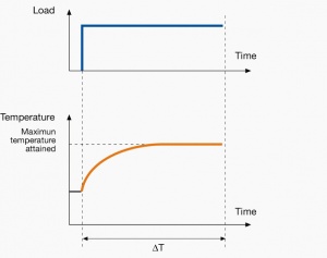
| S1
|
S1
|
Continuous duty
|
The motor is turned on and works at a constant Load for enough time to reach Temperature equilibrium. It then keeps going. An example could be a fan that is turned on and kept on.
|
|
Fans, escalators, eMobility solutions, packaging machinery, paper mill drives compressors, conveyers, centrifugal pumps.
|
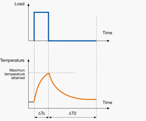
| S2
|
Duty type followed by duration of the duty, e.g. S2 40 minutes.
|
Short-time duty
|
Constant load but not long enough to reach Temperature equilibrium (unlike S1) and instead enters a rest period long enough for the motor to cool down to ambient temperature.
|
|
Crane drivers, drives for household appliances, sluice gate drives, valve drives and machine tool drives.
|
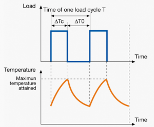
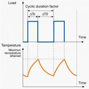
| S3
|
Duty type followed by cyclic duration factor, e.g. S3 30%.
|
Intermittent periodic duty
|
Sequential, identical Run and Rest cycles. The load is constant. Temperature equilibrium is not reached. Unlike S2, the rest periods are not long enough for the motor to cool down to ambient temperature.
|
|
Plastics machinery, food and beverage processing.
|
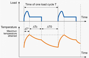
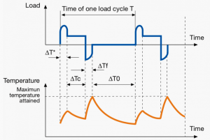
| S4
|
Duty type followed by cyclic duration factor, moment of inertia of the motor JM, and by the moment of inertia of the load JL (both refer to the motor shaft) e.g. S4 20% JM = 0.15 kg m2 JL = 0.7 kg m2.
|
Intermittent periodic duty with starting
|
Sequential, identical Run and Rest cycles. The load is constant but starting uses more current which leads to a rise in temperature. Neither Run and Rest periods are long enough to attain Temperature equilibrium.
|
|
Metal cutting, drilling tool drives, mine hoist drives for lift trucks.
|
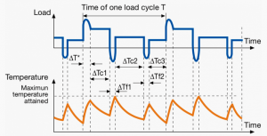
| S5
|
Duty type followed by cyclic duration factor, moment of inertia of the motor JM, and by the moment of inertia of the load JL (both refer to the motor shaft) e.g. S5 20% JM = 0.15 kg m2 JL = 0.7 kg m2.
|
Intermittent periodic duty with electric braking
|
Sequential, identical cycles of Starting, running at constant load, a quick electric braking period, and a period de-energized and at rest. Thermal equilibrium is not reached in one duty cycle. Braking is done electrically and is quick.. No rest periods.
|
|
Several machine tool drives, drives for electric suburban trains and mine hoist.
|
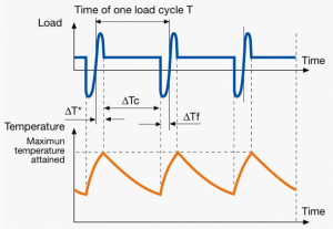
| S6
|
Duty type followed by cyclic duration factor e.g. S6 30%.
|
Continuous operation with intermittent load
|
Sequential, identical cycles of running with constant load and running with no load. No rest periods (unlike S3). Thermal equilibrium is not rached in one duty cycle.
|
|
Pressing, cutting, shearing and drilling machine drives.
|
| S7
|
Duty type followed by moment of inertia of the motor JM and the moment of inertia of the load JL (S7 JM = 0.4 kg m2 JL = 7.5 kg m2).
|
Continuous operation with electric braking
|
Sequential identical cycles of starting, running at constant load and electric braking. No rest periods.
|
|
Blooming mills for steel manufacturing, supply chain machinery across material handling, some medical technologies, including precision applications.
|
| S8
|
Duty type followed by moment of inertia of the motor JM, moment of inertia of the load JL, load, speed and cyclic duration factor, for each speed condition (S8 JM = 0.7 kg m2JL = 8kgm2 25kW 800rpm 25% 40kW 1250rpm 20% 25 kW 1000 rpm 55%).
|
Continuous operation with periodic changes in load and speed
|
Identical duty cycles, each consisting of a time of operation at constant load corresponding to a predetermined speed of rotation, followed by one or more times of operation at other constant loads corresponding to different speeds of rotation. No rest periods.
|
|
|
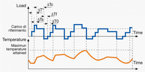
| S9
|
S9
|
Duty with non-periodic load and speed variations
|
Motor is run non-periodically with varying load and speed within the permissible operating range. This duty includes frequently appplied overloads which may greatly exceed the reference load.
|
|
|
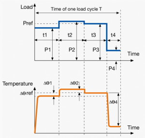
| S10
|
Duty type followed by per unit quantities p/Δt for the partial load and its duration, per unit quantity TL which represents the thermal life expectancy of the insulation system related to thermal life expectancy in case of duty type S1 with rated output, and by quantity r which indicates load for a time de-energized and at rest, e.g. S10 p/Δt = 1.1/0.4; 1/0.3; 0.9/0.2; r/0.1 TL = 0.6.
|
Duty with discrete constant loads and speeds
|
A specific number of discrete values of load maintained for a sufficient time to allow the machine to reach thermal equilibrium. The minimum load during a duty cycle may have value zero and be relevant to a no- load or rest condition.
|
|
|
Step 3) Dimension the motor
Once the motor type has been selected, the motor has to be "dimensioned" or "sized." This means that we need to select a motor that is of the right size and power.
An underdimensioned motor will not provide enough torque for the intended application to be performed or be under too much stress leading to a reduced lifespan for the motor. A motor that is overdimensioned will cost more than needed, increase energy usage and be inefficient.
The steps for dimensioning the motor will depend on the which motor type was selected in Step 2 of this article. Follow the link to the dimensioning guide correspodning to the selected motor type below:
See also
Machine elements
Machine elements section under Basic calculations


