Servomotor dimensioning
The dimensioning, aka sizing, of a servomotor includes the following steps (which are described in further detail on this page):
- Step 1) Define Load requirement
- Step 1.1) Load calculation
- Step 1.2) Mechanism calculation (skip to the sub-section that corresponds to the Drive mechanism that was selected as a prerequisite.)
- Step 1.3) Transmission calculation
- Step 2) Define Motion requirements
- Step 3) Select qualifying motor from product catalog
Step 1) Define Load requirement
Now that we have selected the motor type, the motor has to be dimensioned. That means we need to conclude how powerful the motor must be in order to perform the intended task. If the motor is under-dimensioned, it won't be powerful enough to perform the intended task. If the motor is over-dimensioned, it's price and operation cost will be too high.
These are the sub-steps for dimensioning the motor:
- Step 1.1) Load calculation
- Step 1.2) Mechanism calculation
- Step 1.3) Transmission calculation
Dimensioning the motor can either be done manually or by using a Motor Dimensioning Software (also referred to as motor selection software.)
Step 1.1) Load calculation
The Load is constituted by
- The Mass of the object that the motor is intended to move (this does not include the mechanism which is covered in the next step.)
- External Forces that will require more work to be performed by the motor.
Note the Mass of the object that motor is intended to move.
Note any External Forces that will require more work to be performed by the motor.
Step 1.2) Drive mechanism calculation
The motor must not only be strong enough to move the Load - it must be strong enough to move the Mechanism the the Load is applied to. For example, if the application is a belt conveyor intended to move boxes from one end to another, the motor will have to be strong enough to move the boxes that together make up the Load (covered in the step above), plus the Mechanism which includes the belt as well as the wheel that drives the belt.
Depending on the type of Drive mechanism, there are usually two parameters of interest:
- the Mass of the mechanism and
- the Moment of Intertia of the mechanism
Moment of Inertia is a measurement of how much effort is required to rotate an object. The Moment of Inertia for an object is determined by:
- The rotational axis relative to the object
- The shape and size of the object
- The mass of the object
Jump to the sub-chapter corresponding to the selected drive according to the list below:
| Mechanism | Jump to step |
|---|---|
| Belt Drive | Step 1.2.1 |
| Ball Screw | Step 1.2.2 |
| Chain and Sprocket | Step 1.2.3 |
| Rack and Pinion | Step 1.2.4 |
| Linear Motor | Step 1.2.5 |
| Roll Feeder | Step 1.2.6 |
| Rotational Table | Step 1.2.7 |
| Crank | Step 1.2.8 |
Step 1.2.1 Belt Drive
In a Belt Drive the motor is coupled to a timing pulley that drives a flexible toothed belt, with its coupled load, back and forth between two idler pulley guides.
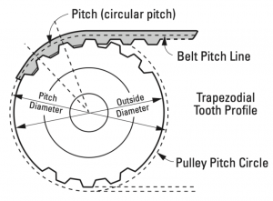
Step 1.2.1.1 Note pitch diameter
The Driver Pitch Diameter is slightly larger than the outer diameter of the pulley and corresponds to the pitch line of the belt which is the line formed by the belt’s tensile cord.
The Pitch Diameter value can be used to calculate a rotational to linear ratio as given by:
V = ω * (D / 2)
where
V = rotational to linear ratio
D = Pitch Diameter
ω = the angular speed measured in radians per second
Step 1.2.1.2 Note Belt Mass
Belt Mass is the mass of the belt including any objects that are moving the load linearly. The Load (calculated in Step 2.1) is excluded from belt mass.
Step 1.2.1.3 Note Driver/Idler Inertia
Driver/Idler Inertia is the inertia of the mechanism that moves the load. This includes any rotationally moving parts that are not a part of the motor or transmission.
Step 1.2.1.4 Note Efficiency
Mechanical efficiency is measured as the ratio of the measured performance to the performance of an ideal machine. It is entered as a value between 0 and 1. See chapter "List of typical mechanical efficiencies" in this article.
Step 1.2.2 Ball Screw
A ball screw is coupled to a rotary motor and causes linear motion between a rotating screw and its non-rotating nut.
Step 1.2.2.1 Note Lead
The Lead is a measurement of the distance that the Load will move linearly with a single full revolution of the screw. The Lead for different ball screws can be found in product catalogs and are normally specified in millimeters.
Step 1.2.2.2 Note Slide Mass
Slide Mass is the mass of the slide including any objects that are moving the load linearly. The Load (calculated in previous steps) is excluded from this mass.
Step 1.2.2.3 Note Ball Screw Inertia
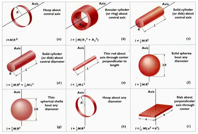
A Ball Screw has a cylindrical shape and will rotate around its central axis and can therefore be calculated like this:
I = 1/2 * m * r^2
where
I = Moment of Inertia
m = Mass
r = Radius
For a graphical explanation, see figure C in the chapter "Table of equations for Moment of Inertia for different shapes" in this article.
If the mass is not known, the following formula can be used:
I = (π/32) * D^4*ρ*L
where
I = Moment of Inertia
ρ = Density for the material that the Ball Screw is made from
L = Length
Step 1.2.2.4 Note Coupling Inertia
If Couplings are attached to the Ball Screw, their Moment of Inertia must be factored in the same way as for the Ball Screw covered in the step above.
Step 1.2.2.5 Note Efficiency
Mechanical efficiency is measured as the ratio of the measured performance to the performance of an ideal machine. It is entered as a value between 0 and 1. See chapter "List of typical mechanical efficiencies" in this article.
Step 1.2.3 Chain and Sprocket
A chain and sprocket is a rotary motor coupled to a sprocket wheel that drives a linked chain, with its coupled load, back and forth between idler sprocket guides.
Step 1.2.3.1 Note Sprocket Pitch Circle Diameter
Sprocket Pitch Circle Diameter is a measure of the diameter that the chain moves about. This value is used to calculate a rotational to linear ratio as given by:
V = ω * (D / 2)
where
V = rotational to linear ratio
D = Pitch Diameter
ω = the angular speed measured in radians per second
Step 1.2.3.2 Note Chain Mass
Chain Mass is the mass of the chain including any objects that are moving the load linearly. The Load (calculated in previous steps) is excluded from this mass.
Step 1.2.3.3 Note Sprocket/Idler Inertia
Sprocket/Idler Inertia is the inertia of the mechanism that moves the load. This includes any rotationally moving parts that are not a part of the motor or transmission.
Step 1.2.3.4 Note Efficiency
Mechanical efficiency is measured as the ratio of the measured performance to the performance of an ideal machine. It is entered as a value between 0 and 1. See chapter "List of typical mechanical efficiencies" in this article.
Step 1.2.4 Rack and Pinion
A rack and pinion is a rotary motor coupled to a toothed pinion wheel that engages a toothed rack to create relative motion between the two elements.
Step 1.2.4.1 Note Pinion Pitch Circle Diameter
Pinion Pitch Circle Diameter is a measure of the diameter that the rack moves about. This value is used to calculate a rotational to linear ratio as given by:
V = ω * (D / 2)
where
V = rotational to linear ratio
D = Pitch Diameter
ω = the angular speed measured in radians per second
Step 1.2.4.2 Note Rack Mass
Rack Mass is the mass of the Rack including any objects that are moving the load linearly. The Load (calculated in previous steps) is excluded from this mass.
Step 1.2.4.3 Note Pinion Inertia
Pinion Inertia is the inertia of the mechanism that moves the load. This includes any rotationally moving parts that are not a part of the motor or transmission.
Step 1.2.4.4 Note Efficiency
Mechanical efficiency is measured as the ratio of the measured performance to the performance of an ideal machine. It is entered as a value between 0 and 1. See chapter "List of typical mechanical efficiencies" in this article.
Step 1.2.5 Linear Motor
Linear motors are either iron-core and ironless motors that directly create linear thrust. Their separate sections (coil and magnet channel) produce relative motion between a carriage and its base along linear bearing guides.
Step 1.2.5.1 Note Force margin
Force margin (Km) – This is a coefficient for cases that have increased required force to accelerate or decelerate. This is based on the structure of a machine. Input a value of 1 or more based on the inertia of the moving coil and the center of gravity of load. Force to accelerate or decelerate is calculated as F = Km•m•a.
Step 1.2.5.2 Note Slide Mass
Slide Mass is the mass of the slide including any objects that are moving the load linearly. The Load (calculated in previous steps) is excluded from this mass.
Step 1.2.6 Roll Feeder
A Roll Feeder is a mechanism that continuously feeds material through rollers.
Step 1.2.6.1 Note Driver Pitch Diameter
Driver Pitch Diameter is a measure of the diameter that the material moves about. This value is used to calculate a rotational to linear ratio as given by:
V = ω * (D / 2)
where
V = rotational to linear ratio
D = Pitch Diameter
ω = the angular speed measured in radians per second
Step 1.2.6.2 Note Driving Roller Inertia
Driving Roller Inertia is the inertia of the roller that moves the material.
Step 1.2.6.3 Note Driven Roller Inertia
Driven Roller Inertia is the inertia of the roller(s) that freely spin with the material. This includes any rotationally moving parts that are not being driven by the motor. If the pitch diameters of the rollers differ from that of the driving roller the ratio between the two must be factored in.
Step 1.2.6.4 Note Efficiency
Mechanical efficiency is measured as the ratio of the measured performance to the performance of an ideal machine. It is entered as a value between 0 and 1. See chapter "List of typical mechanical efficiencies" in this article.
Step 1.2.7 Rotational Table
A rotational table is a mechanism where the primary load is moving rotationally. There is no mechanism coupling the load to the motor/transmission.
Step 1.2.8 Crank
The crank mechanism translates rotational motion of the crank arm into reciprocating linear motion via a connecting rod.
Step 1.2.8.1 Note Crank Radius
Crank Radius is the radius from the center of rotation to the pin that connects to the connecting rod.
Step 1.2.8.2 Note Connecting Rod Length
Connecting Rod Length is the distance from the pin that connects to the crank to the pin that connects to the load.
Step 1.2.8.3 Note Crank Inertia
Crank Inertia is the inertia of the mechanism that moves the load. This includes any rotationally moving parts that are not a part of the motor or transmission.
Step 1.2.8.4 Note Efficiency
Mechanical efficiency is measured as the ratio of the measured performance to the performance of an ideal machine. It is entered as a value between 0 and 1. See chapter "List of typical mechanical efficiencies" in this article.
Step 1.3) Select gearing
In a lot of machines, the motor is capable of much higher speeds than required. At the same time, a motor may not be able to provide the required torque. Therefore, gearing is applied to the motor.
When selecting gearing for a motor, the gearing is commonly refereed to as a Reducer, which can also be referred to as a Gear Reducer, Speed Reducer, or Gearbox. It consists of a number of mated gears. A Reducer is connected to a motor and uses the mechanical advantage of gears to enable the following functions:
- Reduce speed
- Increase torque
A reducer's rated output torque, that is the torque that the reducer is capable of delivering, shall exceed the required torque of the intended application. Otherwise, the reducer can break or performance can decline rapidly.
The Gear ratio can be calculated like this:
Gear ratio = motor speed / required speed
For example, a motor with a speed of 500 rpm and a gearbox with a 10:1 gear ratio would result in and output speed of 50 rpm.
Then the new required torque must be calculated like this:
New required torque = initial required torque / gear ratio
Gearbox Output Torque can be calculated with the following equation:
Output Torque = Motor Output Torque * Gearbox Ratio * Gearbox efficiency
See Gear for additional info and gear calculation.
Step 2) Define Motion requirements by defining Motion profile
Besides defining the Load requirement (in earlier steps), we must also define the requirement for the Motion of the drive-mechanism carrying that Load. Just because a motor can provide enough torque for a mechanism to move an object that weighs 20 kilos doesn’t necessarily mean it is able to do so in for example a restricted time frame of 3 seconds over a distance of 400 mm. Therefore we must define such motion requirements via something called a Motion profile.
A Motion profile is a representation of a Drive-mechanism’s movement, or motion requirements, over time in the form of graphs for any of the following variables:
- Position
- Velocity (measured in m/s or mm/s, etc.)
- Acceleration
- Jerk
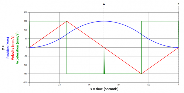
In the example below we see a motion profile for a Slide in a ball screw mechanism. To generate the graphs in the picture, the following requirements were specified:
A) First, from a stand-still, we want the Slide to carry the Load 150 mm in no more than 2 seconds. This position is reached middle of the profile, where it can be read from the blue graph that the Slide has reached it’s max position of 150 mm in 2 seconds. From the red graph, it can be read that the velocity is back at a stand-still; 0 mm/s.
B) After that, we want that motion reversed in the same amount of time; -150 mm in 2 seconds. Just after the dotted line A, we can read from the red graph that the Slide is now speeding up in the reverse direction, represented by negative values in mm/s. At the end of the profile, when another 2 seconds has passed, we can read from the blue graph that the Slide has returned to it’s orginal position of 0 mm. The table below shows the input for the Motion profile graphs. (The ”Type” indicated as ”Triangle” is explained below the graphs.)
| Type | Time (s) | Position (mm) | External force |
|---|---|---|---|
| N/A; starting position | 0 | 0 | 0 |
| Triangle | 2 | 150 |
0 |
| Triangle | 4 | 0 | 0 |
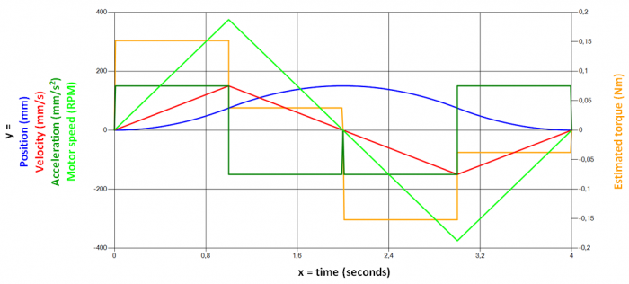
It is common among motor selection softwares to include the functionality of displaying graphs for
- Motor speed
- Estimated torque
superimposed over other motion profile graphs. Below is a motion profile identical to the one above but with Motor speed (measured in revolutions per minute) and Estimated torque (measured in Newton meter)
In the context of a Motion profile, motion can take the following three forms:
In practice, these forms of motion are commonly combined into two main profiles:
The Triangle profile represents acceleration from a stand-still to max speed, followed by deceleration back to a stand-still.
The Trapezoid profile represents acceleration from a stand-still to a max speed that remains constant for some time, followed by deceleration back to a stand-still.
The example profile above is a combination of two triangles, where the second triangle is ”upside down” as the slide is moving in the opposite direction, back to it’s original position.
A motion profile can be any combination of accelerations, constant speeds, and deceleration.
Step 3) Select qualifying motor from product catalog
The final step is to access a motor product catalog and select a motor that fulfills the requirements that were defined in the previous steps. Most motor selection software have such a product catalog embedded in the software where you can filter motors that are with or without a brake, or have an appropriate voltage for your geographical location, etc.
List of typical mechanical efficiencies
• Acme-screw w/brass nut ~ 0.35 - 0.65
• Acme-screw w/plastic nut ~ 0.50 - 0.85
• Ball-screw ~ 0.85 - 0.95
• Preloaded Ball-Screw ~ 0.75 - 0.85
• Spur or Bevel Gears ~ 0.90
• Timing Belts ~ 0.96 - 0.98
• Chain & Sprocket ~ 0.95 - 0.98
• Worm Gears ~ 0.45 - 0.85
Table of equations for Moment of Inertia for different shapes
Moment of Inertia is a measurement of how much torque is required to rotate an object. The Moment of Inertia for an object is determined by:
- The rotational axis relative to the object
- The shape and size of the object
- The mass of the object


