Iconic CAD Workflow Example: Difference between revisions
| (37 intermediate revisions by the same user not shown) | |||
| Line 231: | Line 231: | ||
#Continue until all icons are parsed. | #Continue until all icons are parsed. | ||
=Compile Inkscape SVG to Generate CAD= | ==Compile Inkscape SVG to Generate CAD== | ||
*So far - icons work for square shapes. But - north and south wall are reversed - N in inkscape is south in freecad etc. And last module is missing. | *So far - icons work for square shapes. But - north and south wall are reversed - N in inkscape is south in freecad etc. And last module is missing. | ||
*Sample - [[File:project.zip]]. Chat - [https://chatgpt.com/share/69b250a2-da40-8010-9dfb-46c718a71ca2] | *Sample - [[File:project.zip]]. Chat - [https://chatgpt.com/share/69b250a2-da40-8010-9dfb-46c718a71ca2] | ||
| Line 254: | Line 254: | ||
**Continue until you get back to the finish. The last module ends up on the south side of the West edge of the first north panel. | **Continue until you get back to the finish. The last module ends up on the south side of the West edge of the first north panel. | ||
**It would probably be useful to do a naming convention for labeling these walls from 1 to N, where N is the number of the last module. | **It would probably be useful to do a naming convention for labeling these walls from 1 to N, where N is the number of the last module. | ||
==Icon Validation File== | |||
Is this what the algorithm is doing? Can we do a validator that outputs the parsing of all the walls - in human readable language as above, so that one could verify any obvious mistakes of mis-parsing? | Is this what the algorithm is doing? Can we do a validator that outputs the parsing of all the walls - in human readable language as above, so that one could verify any obvious mistakes of mis-parsing? | ||
*Validation program - [[File:validate_layout | We are now validating that the icon file is being read properly - N, E, W, S walls, orientation of OSB correct, number of walls parsed is correct. | ||
*Validation program - [[File:validate_layout-py.zip]] with SVG file name of housemodel.svg. This returns - itemized list - direction OSB is pointing (+-x, y), and fail status if osb is pointing the wrong way. | |||
**Failed on OSB status - so it is misreading the OSB. | **Failed on OSB status - so it is misreading the OSB. | ||
Now the working files are: | |||
*housemodel.svg | |||
*framed_wall_panel_schema.yaml | |||
*wall_instances.yaml | |||
*cad_library/wall_4x8_2x6_24oc_osb716_south.FCStd, wall_4x8_2x6_16oc_osb716_south.FCStd, and wall_3x8.5_2x6_16oc_osb716_south.FCStd | |||
So far it does - | |||
*Loading schema... | |||
*Loading wall registry... | |||
*Parsing SVG... | |||
*Classifying perimeter sides... | |||
*Ordering clockwise perimeter... | |||
*Resolving wall semantics... | |||
--------------- | |||
SVG wall candidates found: 10 | |||
EXPECTED SIDE COUNTS | |||
-------------------- | |||
north=3 east=2 south=3 west=2 | |||
==Thorough Validation Attempt== | |||
But, the first wall (NW corner which should be N) gives me a 90 degree rotation - but 180 is expected (convention is OSB is on South side). So let's provide incontrovertible rules - '''by spelling out all known rules:''' | |||
Files: | |||
*housemodel.svg | |||
*framed_wall_panel_schema.yaml | |||
*wall_instances.yaml | |||
*cad_library | |||
**wall_4x8_2x6_24oc_osb716_south.FCStd | |||
**wall_4x8_2x6_16oc_osb716_south.FCStd | |||
**wall_3x8.5_2x6_16oc_osb716_south.FCStd | |||
#Originally, we define a schema to produce a part library of FreeCAD files, the schema.yaml. | |||
#Our goal is to generate a compiler for the assembly, the compile_house.py file - which parses the SVG file of icons and converts the iconic representation into real CAD, in FreeCAD format. | |||
#The grid in the SVG file is not the source of dimensional truth for modules - as the modules carry their own parameters for size. | |||
#You are provided with a graph of icons, the housemodel.svg file which represents a real house design. | |||
#You are provided with a cad_library of FreeCAD files, containing wall module instances identified by filename. | |||
#SVG file icons are generated from a schema, and have metadata identifying them by the same name as the FreeCAD files. | |||
#The parameters used in instances of modules are found in the instances.yaml file. | |||
#The snappning grid for image files accepts 64 pixel x 64 pixel icons. | |||
#The icon view corresponds to the real geometry as if looking from above, or the xy plane. | |||
#Icons have their own real dimensions. In case there is a space between icons, such as 2 separate buildings, assume that each grid space is equivalent to 4 feet by 4 feet in real life. | |||
#Wall modules in part library have OSB on south side, or in -y direction. | |||
#Wall module part library standard is OSB -y facing, thus rotations correspond to N, E, W walls. | |||
#South wall instances are just like the walls in the part library, without rotation. | |||
#All south facing walls can only contain translations, but not rotations. | |||
#North walls are represented by icons as icons that are rotated 180 degrees in the SVG file. | |||
#East walls are represented by icons as icons that are rotated 90 degrees clockwise in the SVG file. | |||
#West walls are represented by icons as icons that are rotated 90 degrees clockwise in the SVG file. | |||
#First wall module parsed is North wall on West Side. | |||
#A wall is osverved in the SVG file as a set of icons in a line. | |||
#The count of the icons in a wall is represented by counting the icons in the SVG. | |||
#A corner is marked by the start of another icon but 45 degrees in another direction. | |||
#There are 4 corner details that must be considered: NW, NE, SE, and SW. | |||
#The NW corner has the west wall connect to the south side of the west side of the north wall, inset by the width of the structural lumber plus the thickness of the OSB. For example, the width of 2x6 lumber is 5.5 inches, just like stanard US measurements. 7/16" OSB thickness is the standard. Thus, the inset of the northernmost west wall is 5-15/16" such that the outer surface of west wall and west edge of the north wall are flush with each other. | |||
#The NE corner has the east wall connect to the south side of the east side of the north wall, inset by the width of the structural lumber plus the thickness of the OSB, just like in the NW corner. | |||
#The SE corner has the east wall connect to the north side of the east side of the south wall, inset just like above. | |||
#The SW corner has the west wall connect to the north side of the west side of the south wall, inset just like above. | |||
#This defines all teh corner rules. The OSB rules are that the standard orientation in the part library is south or -y direction. | |||
#This means the OSB faces north on the north walls, or +y direction. | |||
#The OSB faces west on the west walls, or -x direction. | |||
#The OSB faces east on the east walls, or +x direction. | |||
#The number of walls in any direction is at minimum 1, up to any number. | |||
#The above applies to any rectangular shaped building. | |||
#Wall module length (x size in N and S walls, y size in E and W walls) is found in the FreeCAD files, and can be parsed from the instances yaml file. | |||
#Total wall lengths are the sum of all the wall module lengths in each wall. | |||
#In a rectangle-shaped building, the walls must be sized such that the last wall (northernmost west wall) meets the south side of the first wall (the westernmost north wall) as defined in the corner rule. | |||
#This model can be generalized to non-rectangle shaped buildings such as L shaped, and many other variations. | |||
#Some framing systems can consist of 2 or more separate buildings. In such a case, assume that the space in the x and y directions are 4' for each grid space. | |||
#In non-rectangular shaped buildings, assume that any line of icons corresponds to a wall. | |||
#Any time that 2 icons are located 45 degrees from one another, that means a corner. | |||
#There can be 2 corners in a row, which should be interpreted as a building section one module wide. In that case, there is no vertical or horizontal line of icons. | |||
#Any horizontal or vertical line of adjacent icons corresponds to a horizontal or vertical wall. | |||
#Whether a wall is east or west facing is derived from icon rotation as described above. | |||
#'Facing' refers to the orientation of the OSB, meaning + or - x or y, as described above. | |||
#A building can be of any shape, with as many walls as needed, with the only requirement that the last wall connects to the first wall according to the corner rules. | |||
#Compiler from icon graph to FreeCAD should be self-checking, so it outputs the number of walls, then lists them such as north, east, south, west - etc. for a rectangular buildings, and accordingl for other building shapes. Verification should include direction of wall. If number of walls, their direction (n, s, e, w), and OSB direction (+/- x/y) checks out - result should work. | |||
==Next== | |||
It can't parse the file for shit. How to resolve? | |||
New Corner rules: | |||
#parse: icon identity - wall type. | |||
#Icon rotation - just the angle. | |||
#The only logic is: one wall module is next to the next one. | |||
#Connection: If angle is the same, next wall module is in line with the former, joining by the edge stud | |||
#Thus create the first instance in CAD. | |||
#Put the next one to the side, going clockwise from first. | |||
#North wall corner rule: if angle of icon is 180, keep going straight (straight north wall) | |||
#North wall corner rule: if angle changes from 180 to -90, then wall goes south, meaning osb faces East. | |||
#North wall corner rule: if angle changes from 180 to 90, then wall goes north, meaning osb faces West. | |||
...Not the right architecture for corners in more complex building. Simplify: | |||
==Friday== | |||
#parse: icon identity - wall type. | |||
#Icon rotation - just the angle. | |||
#That icon starts the CAD. Parse the icon that is topmost first, and leftmost. For a rectangle, that is West end of north side. For more complex shapes - that is west end of northernmost side. | |||
#The only rule is - parse the next icon. Place in location so that the vertical studs meet each other on the side of the module. | |||
#Go clockwise - read icons clockwise. | |||
#The only requirement for icons is that they are next to each other. This means that icon is located in any adjacent grid continuing in the same direction or making a right angle bend. | |||
#The only logic is: one wall module is next to the next one. | |||
#Connection: If angle is the same, next wall module is in line with the former, joining by the edge stud | |||
#Depending on where the wall is being built, we have rules - keep going or turn 90 degrees. | |||
#Here are the 24 possibilities: | |||
<html> <iframe src="https://docs.google.com/presentation/d/e/2PACX-1vTJxmSi99I3UqYK71V_ixb2zp9zfZgGDIlCovio8vr5Im7v6Sp19cslF4zZhGJb3ROogU66rRayduzH/pubembed?start=false&loop=false&delayms=3000" frameborder="0" width="480" height="389" allowfullscreen="true" mozallowfullscreen="true" webkitallowfullscreen="true"></iframe> </html> | |||
[https://docs.google.com/presentation/d/1qYRFBhIUk9bK4FKEb_on2L5GKOWefswss33hn90-pTo/edit?slide=id.g385327b13a5_0_0#slide=id.g385327b13a5_0_0 edit] | |||
[https://chatgpt.com/share/69b467f4-8200-8010-a8cd-3a2edf0b7357] | |||
Ok, looks like you can parse this correctly. With the 24 possibilities, then we can create a compliler that translates icons which are next to each other by icon identity corresponding to wall type and its parameters. | |||
Icon rotation shows the ange, corresponding to the 4 different classes of cases, each with 3 different wall placements per side, with actually 12 total possibilities because we are parsing in one direction, therefore each of the 4 wall type has only 3 possibilities per wall type, for 12 possibilities total. Do you see this in the next jpg image? [[File:12parse.jpg|50px]] | |||
=Friday Evening= | |||
*Parsing is correct - for example - | |||
CAD PLACEMENT PLAN | |||
All placement coordinates below are shown in inches. | |||
01. side=North module=wall_4x8_2x6_16oc_osb716_south origin=(0.00, 0.00, 0.00) in width=48.00 in next_mode=same-side | |||
02. side=North module=wall_4x8_2x6_16oc_osb716_south origin=(48.00, 0.00, 0.00) in width=48.00 in next_mode=same-side | |||
03. side=North module=wall_3x8.5_2x6_16oc_osb716_south origin=(96.00, 0.00, 0.00) in width=36.00 in next_mode=inside | |||
04. side=East module=wall_4x8_2x6_16oc_osb716_south origin=(132.00, 0.00, 0.00) in width=48.00 in next_mode=same-side | |||
05. side=East module=wall_4x8_2x6_16oc_osb716_south origin=(132.00, -48.00, 0.00) in width=48.00 in next_mode=inside | |||
06. side=South module=wall_3x8.5_2x6_16oc_osb716_south origin=(132.00, -96.00, 0.00) in width=36.00 in next_mode=same-side | |||
*But, actual CAD fails. | |||
==Friday Compiler== | |||
Therefore, the compiler should be simple. First parse icon identity from housedesign.svg to identify wall module. Start at whatever is the topmost and left side of the icon graphic. Icon rotation determines simply which of the 4 cases of walls we have - which direction the OSB faces. Facing rules: N walls OSB +y. S walls OSB -y. E walls OSB +x. W walls OSB -x. | |||
The only rule is - parse the next icon closest to the starting icon, in the clockwise direction. In the real CAD, for simplicity, start the first wall parsed at 0,0,0. Place actual wall in location so that the vertical studs meet each other on the leading side of the starting module. | |||
Go clockwise - read icons clockwise. | |||
The only requirement for icons graph parsing is to identify which icon is next in the clockwise direction. Just search for the next icon clockwise. | |||
The only logic for real CAD is: one wall module is next to the next one. Is this sufficient to translate the icon graph to the house in freeCAD? If so, provide compiler. | |||
==Corner Rule Correction - N-S Walls== | |||
*But this is the correct rule for NS, and it must include notching of OSB in 2 special cases of more complex geometry required for non-recangle-shaped buildings (L, T, stagger, courtyard, etc) : [[File:NSrules.jpg|50px]] | |||
*Post-process - for corners, i think we need to post-attach (or attach in production) OSB cover on the edge: [[File:cornerdete.jpg|100px]] | |||
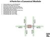
*'''Use ports, defined in schema.''' I got confused because ports are nontrivial - we need to be explicit about joining points - of which there are 6 for a canonical module. | |||
==OSB Angle Determines Notching of OSB== | |||
*[[File:angleandnotch.jpg|100px]] | |||
*Ports don't work, ordering seems poorly parsed. | |||
==Explicit procedure== | |||
#Take the icon in svg with the lowest y coordinate (top-most) and from these select the lowerst X coordinate. This selects the top and left icon. ex. - first_icon = min(icons, key=(y, x)) | |||
#Next icon in North wall: next = min( N_icons where x > current.x , key=x ) | |||
#candidate = min(N icons where x > current.x) | |||
*Another issue - parsing icons is problematic if world icon coordinate is not used, but anchor coordinate is used (bottom left). Must pay attention to anchor vs world coordinate. | |||
*Should we just try 1-1 correspondence in icon library - so each wall (N, S, E, W) has its own icon and there is no confusion on how to parse icons? Just use one direction letter for each wall. | |||
*Maybe ask chat how to do it in the most effective way. | |||
*Payoff is big: public design via abstraction layer of icons. | |||
*Concept: it would also be possible to spell out how to build a house word by word, but that would be hard for the user. It is useful to simply draw - as a picture is worth a thousand words and is mistake proof. | |||
=Post-Process Resulting CAD= | =Post-Process Resulting CAD= | ||
Add corners, blocking. | Add corners, blocking. | ||
Latest revision as of 05:59, 14 March 2026
Iconic CAD Workflow for Wall Modules
- Author wall family schema. Start with human language for a ChatGPT prompt. This prompt, initially, includes geometry parameters. Then it includes ports (interfaces). Then it includes build procedure information. Then it includes materials information - all materials are delineated. . Materials information includes sourcing via web links. Quality Control points including dimensional tolerance.
- Run syntactic validator
- Run semantic validator
- Compile batch of wall modules
- Publish module CAD + icon library
- Arrange icons in graphics tool
- Export to SVG
- Normalize SVG
- Parse icon positions, IDs, rotations, adjacency
- Run assembly syntax validator
- Run assembly semantic validator
- Compile full CAD assembly
- Run post-processing
- Export BOM, cut list, and reports
Iconic CAD Workflow Concept Detail.
Authoring a Wall Family Schema
(based on former design at [1] but only for wall)
Design schema: Ok, let's do wall modules, 4'x9' (wide x height) using 2x6 lumber or 2x4 lumber, which is selectable. In fact, and dimension lumber is selectable from 2x2 to 2x12 lumber. Schema allows me to do 16" or 24" on center. These have 7/16" OSB on one side - the outside. Orientation is given so that 'house faces south' - ie, if you generate the module, the exterior is south, and therefore . This schema allows me to choose module width, and module height as well. Sheets of OSB come in 8 foot lengths, but 9 foot and 10 foot lengths can also be used as standards. Module width is 4' nominal, but can be selected to be lower or larger up to 8'. For a height of 9' or less it uses a single sheet of 9' osb.
Fabrication Schema: From which partial OSB heights and widths can be cut. For anything over 10', we use 8' OSB + whatever more we need - because 8' is easiest to source. For materials, if wall modules are 8, 9, or 10' - use OSB in these dimensions but use precut studs, in which case the OSB is 3/8" longer than the resulting module. In the design of 8, 9, or 10 foot modules, the extra OSB should face up so that panels can be stood on a flat bottom. Do not cut this material off, as cutting is not needed. With moduel
Materials Schema: Lumber: anything from 2x2 to 2x12 lumber, with lengths from 4' to 20'. OSB sheets, 7/16" is the standard. Can also use 1/2", 5/8", and 3/4" OSB.
Fastener Schema: For fasteners, we use 3-1/4" ring shank nails as standard for the wood, and 2-3/8" nails for OSB. Fastener schedule is 6" on perimeter and 12" in the field.
Sourcing Schema: For every material used, we have a link to the best source on the web, + as many other links as needed.
Quality Control + Tolerance Schema: Tolerance is +/- 1/8" off the stock edge of OSB, and 1/8" from the desired length and width of module. No dimensional tolerance on the panel thicknesss because dimensional lumber is used.
Optimization Schema:
Create Part Library: 3 Parts
(just using Design Schema, not Fabrication + other schemas)
| Layer | Implementation | Input | Output | Role |
|---|---|---|---|---|
| Schema | YAML | Engineering definition of module | Parameter + interface specification | Defines the semantic contract of the module |
| Generator | Python (FreeCAD API) | Schema | Parametric geometry function | Converts schema rules into geometry construction |
| Compiler | Python assembly tool | Module instances + transforms | .FCStd assembly file | Instantiates parts and builds assemblies |
Note that to create parts for the part library, 5 files are involved:
| Stage | Type | Description |
|---|---|---|
| Schema | Software + data format | YAML specification defining module semantics |
| Geometry Generator | Software | Python program producing CAD geometry |
| Part Instances | Data artifact | Generated CAD objects or parameterized parts |
| Assembly Compiler | Software | Program assembling modules into a system |
FreeCAD .FCStd
|
Data artifact | Final CAD assembly file |
Acutal Schema
- Wall Schema for Iconic CAD Workflow in YAML
- 3 Instances of Walls in YAML
Process Evolves
| Step | Stage | Description | Example | Notes |
|---|---|---|---|---|
| 1 | Design Schema (parameter space) | Defines the allowable design space for the module family, including parameter definitions, allowed ranges, enums, relationships, and constraints. No specific design values are included. | Wall Schema for Iconic CAD Workflow - framed_wall_panel_schema.yaml - YAML | Schema asks: what is allowed? Instance asks: what is chosen? Semantic validator asks: does the chosen design make sense? -> validate_semantics.py should run on the instances. |
| 2 | Instances | Specifies concrete module designs by assigning values to the parameters defined in the schema. Each instance represents one module to be generated. | 3 Instances of Walls - wall_instances.yaml | |
| 3 | Syntactic Validator | Checks that each instance conforms structurally to the schema: required fields exist, data types are correct, and enum values and ranges are respected. | Wall Syntactic Validator - validate_syntax.py | |
| 4 | Semantic Validator | Verifies that the design is logically and structurally meaningful according to engineering rules (for example, stud spacing fits within panel width, module dimensions are feasible). | Wall Semantic Validator - validate_semantics.py | Chat - [2]. $ python validate_semantics.py wall_instances.yaml -> Semantic validation passed: 3 instance(s) validated successfully. |
| 5 | Design Compiler (derive parameters) | Computes derived design values from the instance parameters and schema rules (for example, stud count, stud locations, panel thickness, and sheathing dimensions). | Wall Design Compiler - generate_wall_library.py | Make sure you have native install of FreeCAD for CLI usage - not flatpak or appimage, which is harder to parse. On Linux Mint - sudo add-apt-repository ppa:freecad-maintainers/freecad-stable
sudo apt update -> sudo apt install freecad. Must run from command line like this - freecadcmd -c "python code here". -> freecadcmd -c "import sys; sys.argv=['generate_wall_library.py','wall_instances.yaml']; exec(open('generate_wall_library.py').read())" |
| 6 | Geometry Generator | Generates the CAD geometry for each validated instance using the derived parameters and design rules, producing CAD models for the module. | Wall Geometry Generator | |
| 7 | Geometry Validator | Verifies that the generated CAD geometry matches the intended design (correct dimensions, stud placement, panel thickness, and valid solid geometry). | Wall Geometry Validator - validate_wall_geometry.py | freecadcmd -c "import sys; sys.argv=['validate_wall_geometry.py','wall_instances.yaml']; exec(open('validate_wall_geometry.py').read())" |
| 8 | CAD Part Library | Stores the compiled CAD modules (for example, .FCStd files) representing validated parametric instances of the module family. | Wall Part Library |
Icon Library Principles
- Use separate schema, do not put this into the CAD schema. This helps to make the process formal or modular - and replicable.
- Human-visible annotation is not the source of truth. Structured schema data is the source of truth. So the right architecture is: icon + machine-readable parameters + optional human-readable annotation not icon + freeform text annotation interpreted by AI
- Summary: Schemas are the reality. Visible labels are only for human readability.
Icon Prompt
Do icon in black lines. Use style from OSE Branding 2026 - [3]. Modify so each icon has an exterior Border which is thick line with rounded corners so we have a box around whatever the icon is. Give me a 2x6 24OC icon, 2x6 16OC icon, then 2x6 3'x8.5' 16OC. You can represent 24 OC as wall module with 3 studs, and 16 OC as wall module with 4 studs. To represent 2x6, just use 2x6 as the label. To show 3'x8.5', use that as a text label.
Icons
- SVG format
- 3 examples + Inkscape snapping template - File:Iconic cad icons.zip
Manipulate Icons in Inkscape
- Imported the 64 pixel template
- File:

- Initial issue - clean snap. Deselect and hold by corner to snap to grid. But, after moving a few, one of the icons is a few pixels off grid. WT?
- Make sure to enable snapping with bounding boxes in Inkscape (upper right magnet icon)
Prompt for Taking Iconic Drawing - and Converting to FreeCAD
Prompt: Ok now to generate a house from the icons, we need AI to parse the icons for their identity. Each icon already has metadata such as wall_2x6_3x8_5_16oc. We also have a CAD library (3 parts) with corresponding names. If i give AI these files (upload of fcstd files) then AI should be able to convert the icons into full CAD. There are a few conventions, such as the wall module standard faces south (exterior OSB faces south). To represent E and W wall, we rotate 90 degrees clockwise for West walls, and 90 degrees counterclockwise for East walls. Furher, the North wall is a standard module icon rotated 180 degrees. Each CAD has 'ports' defined in the schema - attach a wall to either side (vertical studs). For the north and south wall - these protrude such that the E and W walls are inset between these. How to compile this?
Iconic CAD Compilation Pipeline
SVG assembly
→ parse grouped icons
→ read metadata / IDs
→ identify module family
→ read transform (x, y, rotation)
→ instantiate matching CAD part
→ rotate CAD to match wall orientation
→ compute port-to-port joins
→ apply corner convention
→ place all parts in FreeCAD
→ fuse or keep as assembly
→ export FCStd / STEP / BOM
- Needs assembly_rules.yaml
- corner rules
- wall protrusion policy
- join precedence - N + S overlap E + W corners (E and W are inset between N and S walls)
Give Me Compiler
Prompt: Give me compiler to parse the SVG file and produce real CAD from it, and instructions for how to use this compiler.
Ok, so i am providing - FreeCAD parts which have been generated before. The house1.svg which contains the layout of the house framing expressed by icons. Then the schema for the original CAD for the 3 wall modules, framed_wall_panel_schema.yaml. Then the actual 3 instances of walls - wall_instances.yaml. Compiler that I used to convert the CAD schema to the wall wall panel library is not necessary.
I have house1.svg framed_wall_panel_schema.yaml wall_instances.yaml cad_library/wall_4x8_2x6_24oc_osb716_south.FCStd, wall_4x8_2x6_16oc_osb716_south.FCStd, and wall_3x8.5_2x6_16oc_osb716_south.FCStd
NOTE: had to add icon metadata (module name) as XML inside the inkscape working doc. This could have been automated with an icon generation schema.
Process
Initially, chat gave me a postition-based compiler, not a port-based compiler. The latter is more robust - it mimics the actual build process for placing one module against the next.
Position-based compiler script converts a semantic SVG house layout into an assembled FreeCAD model by mapping wall icons to wall modules, applying placement transforms, and exporting the final assembly as a FreeCAD file.
House1meta.svg -
→ finds each wall icon instance in the SVG
→ reads which wall module each icon represents
→ reads the placement of each icon
→ reads the rotation of each icon
→ opens the matching FreeCAD wall part for that module
→ inserts that part into a new FreeCAD document at the correct position and orientation
→ saves the assembled result as house.FCStd

Process 2
Above process algorithm is bad. You cannot get CAD coordinates of placement from SVG. Not all walls are same width. New algorithm: seed from the bottom-left icon, place that CAD part at (0,0,0), then place all other walls relative to already placed walls using adjacency, orientation, real part dimensions, and the inset/protrusion rule.
Precise Concept for Translation of SVG to FCSTD
- Parse identity of icon and its orientation. Note that i had to enter icon metadata automatically, because icons were generated without a schema (just AI prompt). We should use wall_instances.yaml to generate the icons as well - as we want to pass a name equivalent to the CAD file name to the SVG icons.
- Identify corresponding FreeCAD part library
- In part library schema, parse ports
- Determine how to implement ports - interface to the next file
- Continue until all icons are parsed.
Compile Inkscape SVG to Generate CAD
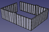
- So far - icons work for square shapes. But - north and south wall are reversed - N in inkscape is south in freecad etc. And last module is missing.
- Sample - File:Project.zip. Chat - [4]
Next Steps - Thursday
- So far a simple square example works where we can program the icons to generate CAD. For one, the last module is forgotten:
- N + S wall reversed.
- Instead of going blindly forward in terms of debugging, I think we should gain full clarity on the algorithm:
- How is the SVG being parsed - and can we simply write a script: start with the upper left E-W module, move clockwise.
- Extract the icon identity, buffer it.
- Go to the end clockwise around the floor plan.
- With all identities buffered - now detail the corners.
- First corner - NW corner - nothing there - as the first wall module stretches E-W - there is no corner until more walls arise.
- Simply place the first wall module, starting at 0, 0, 0. The OSB faces to +Y, which means exterior of building.
- Place the second module to the right at X equal the width of the first module.
- Continue this to the right - going East - until corner.
- At corner, the rule is that East and West walls are inset. Thus, the East Wall is placed on the inside (south) of the last east-west wall panel, with the first East wall inset by the width of the lumber + width of the OSB so that the exterior of the house does not have a step formed by the OSB
- Continue to southeast corner. The first south wall is placed with the east edge of the wall flush with the last East panel OSB.
- Continue left (going West) until the 3rd corner.
- First West wall has its exterior OSB flush with the framing of the last south wall.
- Continue until you get back to the finish. The last module ends up on the south side of the West edge of the first north panel.
- It would probably be useful to do a naming convention for labeling these walls from 1 to N, where N is the number of the last module.


Icon Validation File
Is this what the algorithm is doing? Can we do a validator that outputs the parsing of all the walls - in human readable language as above, so that one could verify any obvious mistakes of mis-parsing?
We are now validating that the icon file is being read properly - N, E, W, S walls, orientation of OSB correct, number of walls parsed is correct.
- Validation program - File:Validate layout-py.zip with SVG file name of housemodel.svg. This returns - itemized list - direction OSB is pointing (+-x, y), and fail status if osb is pointing the wrong way.
- Failed on OSB status - so it is misreading the OSB.
Now the working files are:
- housemodel.svg
- framed_wall_panel_schema.yaml
- wall_instances.yaml
- cad_library/wall_4x8_2x6_24oc_osb716_south.FCStd, wall_4x8_2x6_16oc_osb716_south.FCStd, and wall_3x8.5_2x6_16oc_osb716_south.FCStd
So far it does -
- Loading schema...
- Loading wall registry...
- Parsing SVG...
- Classifying perimeter sides...
- Ordering clockwise perimeter...
- Resolving wall semantics...
SVG wall candidates found: 10
EXPECTED SIDE COUNTS
north=3 east=2 south=3 west=2
Thorough Validation Attempt
But, the first wall (NW corner which should be N) gives me a 90 degree rotation - but 180 is expected (convention is OSB is on South side). So let's provide incontrovertible rules - by spelling out all known rules:
Files:
- housemodel.svg
- framed_wall_panel_schema.yaml
- wall_instances.yaml
- cad_library
- wall_4x8_2x6_24oc_osb716_south.FCStd
- wall_4x8_2x6_16oc_osb716_south.FCStd
- wall_3x8.5_2x6_16oc_osb716_south.FCStd
- Originally, we define a schema to produce a part library of FreeCAD files, the schema.yaml.
- Our goal is to generate a compiler for the assembly, the compile_house.py file - which parses the SVG file of icons and converts the iconic representation into real CAD, in FreeCAD format.
- The grid in the SVG file is not the source of dimensional truth for modules - as the modules carry their own parameters for size.
- You are provided with a graph of icons, the housemodel.svg file which represents a real house design.
- You are provided with a cad_library of FreeCAD files, containing wall module instances identified by filename.
- SVG file icons are generated from a schema, and have metadata identifying them by the same name as the FreeCAD files.
- The parameters used in instances of modules are found in the instances.yaml file.
- The snappning grid for image files accepts 64 pixel x 64 pixel icons.
- The icon view corresponds to the real geometry as if looking from above, or the xy plane.
- Icons have their own real dimensions. In case there is a space between icons, such as 2 separate buildings, assume that each grid space is equivalent to 4 feet by 4 feet in real life.
- Wall modules in part library have OSB on south side, or in -y direction.
- Wall module part library standard is OSB -y facing, thus rotations correspond to N, E, W walls.
- South wall instances are just like the walls in the part library, without rotation.
- All south facing walls can only contain translations, but not rotations.
- North walls are represented by icons as icons that are rotated 180 degrees in the SVG file.
- East walls are represented by icons as icons that are rotated 90 degrees clockwise in the SVG file.
- West walls are represented by icons as icons that are rotated 90 degrees clockwise in the SVG file.
- First wall module parsed is North wall on West Side.
- A wall is osverved in the SVG file as a set of icons in a line.
- The count of the icons in a wall is represented by counting the icons in the SVG.
- A corner is marked by the start of another icon but 45 degrees in another direction.
- There are 4 corner details that must be considered: NW, NE, SE, and SW.
- The NW corner has the west wall connect to the south side of the west side of the north wall, inset by the width of the structural lumber plus the thickness of the OSB. For example, the width of 2x6 lumber is 5.5 inches, just like stanard US measurements. 7/16" OSB thickness is the standard. Thus, the inset of the northernmost west wall is 5-15/16" such that the outer surface of west wall and west edge of the north wall are flush with each other.
- The NE corner has the east wall connect to the south side of the east side of the north wall, inset by the width of the structural lumber plus the thickness of the OSB, just like in the NW corner.
- The SE corner has the east wall connect to the north side of the east side of the south wall, inset just like above.
- The SW corner has the west wall connect to the north side of the west side of the south wall, inset just like above.
- This defines all teh corner rules. The OSB rules are that the standard orientation in the part library is south or -y direction.
- This means the OSB faces north on the north walls, or +y direction.
- The OSB faces west on the west walls, or -x direction.
- The OSB faces east on the east walls, or +x direction.
- The number of walls in any direction is at minimum 1, up to any number.
- The above applies to any rectangular shaped building.
- Wall module length (x size in N and S walls, y size in E and W walls) is found in the FreeCAD files, and can be parsed from the instances yaml file.
- Total wall lengths are the sum of all the wall module lengths in each wall.
- In a rectangle-shaped building, the walls must be sized such that the last wall (northernmost west wall) meets the south side of the first wall (the westernmost north wall) as defined in the corner rule.
- This model can be generalized to non-rectangle shaped buildings such as L shaped, and many other variations.
- Some framing systems can consist of 2 or more separate buildings. In such a case, assume that the space in the x and y directions are 4' for each grid space.
- In non-rectangular shaped buildings, assume that any line of icons corresponds to a wall.
- Any time that 2 icons are located 45 degrees from one another, that means a corner.
- There can be 2 corners in a row, which should be interpreted as a building section one module wide. In that case, there is no vertical or horizontal line of icons.
- Any horizontal or vertical line of adjacent icons corresponds to a horizontal or vertical wall.
- Whether a wall is east or west facing is derived from icon rotation as described above.
- 'Facing' refers to the orientation of the OSB, meaning + or - x or y, as described above.
- A building can be of any shape, with as many walls as needed, with the only requirement that the last wall connects to the first wall according to the corner rules.
- Compiler from icon graph to FreeCAD should be self-checking, so it outputs the number of walls, then lists them such as north, east, south, west - etc. for a rectangular buildings, and accordingl for other building shapes. Verification should include direction of wall. If number of walls, their direction (n, s, e, w), and OSB direction (+/- x/y) checks out - result should work.
Next
It can't parse the file for shit. How to resolve?
New Corner rules:
- parse: icon identity - wall type.
- Icon rotation - just the angle.
- The only logic is: one wall module is next to the next one.
- Connection: If angle is the same, next wall module is in line with the former, joining by the edge stud
- Thus create the first instance in CAD.
- Put the next one to the side, going clockwise from first.
- North wall corner rule: if angle of icon is 180, keep going straight (straight north wall)
- North wall corner rule: if angle changes from 180 to -90, then wall goes south, meaning osb faces East.
- North wall corner rule: if angle changes from 180 to 90, then wall goes north, meaning osb faces West.
...Not the right architecture for corners in more complex building. Simplify:
Friday
- parse: icon identity - wall type.
- Icon rotation - just the angle.
- That icon starts the CAD. Parse the icon that is topmost first, and leftmost. For a rectangle, that is West end of north side. For more complex shapes - that is west end of northernmost side.
- The only rule is - parse the next icon. Place in location so that the vertical studs meet each other on the side of the module.
- Go clockwise - read icons clockwise.
- The only requirement for icons is that they are next to each other. This means that icon is located in any adjacent grid continuing in the same direction or making a right angle bend.
- The only logic is: one wall module is next to the next one.
- Connection: If angle is the same, next wall module is in line with the former, joining by the edge stud
- Depending on where the wall is being built, we have rules - keep going or turn 90 degrees.
- Here are the 24 possibilities:
Ok, looks like you can parse this correctly. With the 24 possibilities, then we can create a compliler that translates icons which are next to each other by icon identity corresponding to wall type and its parameters.
Icon rotation shows the ange, corresponding to the 4 different classes of cases, each with 3 different wall placements per side, with actually 12 total possibilities because we are parsing in one direction, therefore each of the 4 wall type has only 3 possibilities per wall type, for 12 possibilities total. Do you see this in the next jpg image? ![]()
Friday Evening
- Parsing is correct - for example -
CAD PLACEMENT PLAN
All placement coordinates below are shown in inches.
01. side=North module=wall_4x8_2x6_16oc_osb716_south origin=(0.00, 0.00, 0.00) in width=48.00 in next_mode=same-side 02. side=North module=wall_4x8_2x6_16oc_osb716_south origin=(48.00, 0.00, 0.00) in width=48.00 in next_mode=same-side 03. side=North module=wall_3x8.5_2x6_16oc_osb716_south origin=(96.00, 0.00, 0.00) in width=36.00 in next_mode=inside 04. side=East module=wall_4x8_2x6_16oc_osb716_south origin=(132.00, 0.00, 0.00) in width=48.00 in next_mode=same-side 05. side=East module=wall_4x8_2x6_16oc_osb716_south origin=(132.00, -48.00, 0.00) in width=48.00 in next_mode=inside 06. side=South module=wall_3x8.5_2x6_16oc_osb716_south origin=(132.00, -96.00, 0.00) in width=36.00 in next_mode=same-side
- But, actual CAD fails.
Friday Compiler
Therefore, the compiler should be simple. First parse icon identity from housedesign.svg to identify wall module. Start at whatever is the topmost and left side of the icon graphic. Icon rotation determines simply which of the 4 cases of walls we have - which direction the OSB faces. Facing rules: N walls OSB +y. S walls OSB -y. E walls OSB +x. W walls OSB -x. The only rule is - parse the next icon closest to the starting icon, in the clockwise direction. In the real CAD, for simplicity, start the first wall parsed at 0,0,0. Place actual wall in location so that the vertical studs meet each other on the leading side of the starting module. Go clockwise - read icons clockwise. The only requirement for icons graph parsing is to identify which icon is next in the clockwise direction. Just search for the next icon clockwise. The only logic for real CAD is: one wall module is next to the next one. Is this sufficient to translate the icon graph to the house in freeCAD? If so, provide compiler.
Corner Rule Correction - N-S Walls
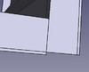
- But this is the correct rule for NS, and it must include notching of OSB in 2 special cases of more complex geometry required for non-recangle-shaped buildings (L, T, stagger, courtyard, etc) :

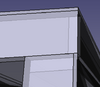
- Post-process - for corners, i think we need to post-attach (or attach in production) OSB cover on the edge:
- Use ports, defined in schema. I got confused because ports are nontrivial - we need to be explicit about joining points - of which there are 6 for a canonical module.

OSB Angle Determines Notching of OSB
- Ports don't work, ordering seems poorly parsed.

Explicit procedure
- Take the icon in svg with the lowest y coordinate (top-most) and from these select the lowerst X coordinate. This selects the top and left icon. ex. - first_icon = min(icons, key=(y, x))
- Next icon in North wall: next = min( N_icons where x > current.x , key=x )
- candidate = min(N icons where x > current.x)
- Another issue - parsing icons is problematic if world icon coordinate is not used, but anchor coordinate is used (bottom left). Must pay attention to anchor vs world coordinate.
- Should we just try 1-1 correspondence in icon library - so each wall (N, S, E, W) has its own icon and there is no confusion on how to parse icons? Just use one direction letter for each wall.
- Maybe ask chat how to do it in the most effective way.
- Payoff is big: public design via abstraction layer of icons.
- Concept: it would also be possible to spell out how to build a house word by word, but that would be hard for the user. It is useful to simply draw - as a picture is worth a thousand words and is mistake proof.
Post-Process Resulting CAD
Add corners, blocking.