PowerCube Wiring: Difference between revisions
Jump to navigation
Jump to search
No edit summary |
No edit summary |
||
| (4 intermediate revisions by 2 users not shown) | |||
| Line 4: | Line 4: | ||
* Connect the remaining wires, as in the diagram below: | * Connect the remaining wires, as in the diagram below: | ||
::[[Image:wiringdiagram.png]] | ::[[Image:wiringdiagram.png]] | ||
Wiring Diagrams: | Wiring Diagrams: | ||
*[http://www.stens.com/images/catalog2/430-249_2_C.jpg Wiring Diagram for Prime Line SBRAI ignition switch] | *[http://www.stens.com/images/catalog2/430-249_2_C.jpg Wiring Diagram for Prime Line SBRAI ignition switch] | ||
*[http://www.mytractorforum.com/showthread.php?t=216425 For More Information] | *[http://www.mytractorforum.com/showthread.php?t=216425 For More Information] | ||
*Terminal letters are decoded as follows: | |||
**B - Battery | |||
**A - Accessory | |||
**R - Regulator | |||
**S - Starter Solenoid | |||
**M - Magneto | |||
**I - Ignition | |||
* Note that the thicker lines represent the heavier wires that will carry high electrical current. | * Note that the thicker lines represent the heavier wires that will carry high electrical current. | ||
===Operation=== | |||
* The Magneto is connected to ground in order to kill the engine | |||
[[category:Power Cube]] | |||
Latest revision as of 22:40, 27 December 2013
Wiring
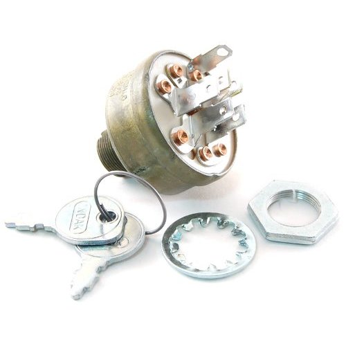
- The keyswitch has spade connectors for wiring and bolts to the frame for stability. These should be connected with matching crimp-on connectors.
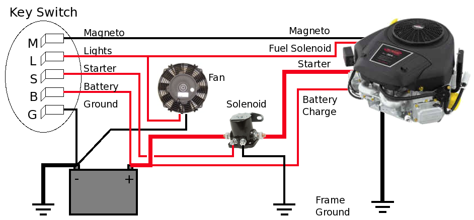
- Connect the remaining wires, as in the diagram below:
Wiring Diagrams:
- Wiring Diagram for Prime Line SBRAI ignition switch
- For More Information
- Terminal letters are decoded as follows:
- B - Battery
- A - Accessory
- R - Regulator
- S - Starter Solenoid
- M - Magneto
- I - Ignition
- Note that the thicker lines represent the heavier wires that will carry high electrical current.
Operation
- The Magneto is connected to ground in order to kill the engine

