Hall Effect Sensor Module: Difference between revisions
| (10 intermediate revisions by 3 users not shown) | |||
| Line 1: | Line 1: | ||
=Introduction= | =Introduction= | ||
You know how a magnet has a magnetic field with a north pole and a south pole? | |||
= | A hall effect sensor outputs an electrical signal that depends on how magnetic fields interact with the sensor. | ||
[[Image: | |||
The hall effect sensor usually has 2 possible output values that are "latching". That means the sensor outputs a low voltage or high voltage signal and continues to do so until the magnetic field of an opposite polarity passes by. | |||
For example, the hall effect sensor is turned on in the "low-latched state". The sensor will continuously output the low value, ex. 0V. Now pass the north pole of a magnet over the sensor. If nothing happens, you know that the "low-latch state" occurs with the north pole. Now pass the south pole of a magnet over the sensor. The sensor now should change into the "high-latched state" and continuously output the high value ex. 1V until a magnet's south pole comes near the sensor to "latch" it into another state. | |||
=Sensor and Holder Assembly= | |||
Installed on CEB Press. Adjustable for proximity to magnets, and up-down adjustable via clamp mechanism. Threaded rod is 3/4", and 2 bolts hold it firmly in place. Known bug: clamp mechanism around frame needs to use 2 - not 1 - bolts for clamping, otherwise rotation around bolt exists. | |||
[[Image:sensorlarge.jpg|400px]] | |||
[[Image: halleffectsensor1.jpg|200px]] | [[Image: halleffectsensor1.jpg|200px]] | ||
[[Image: halleffectsensor2.jpg|200px]] | [[Image: halleffectsensor2.jpg|200px]] | ||
[[Image: halleffectsensor3.jpg|200px]] | [[Image: halleffectsensor3.jpg|200px]] | ||
[[Image: halleffectsensor5.jpg| | [[Image: halleffectsensor5.jpg|200px]] | ||
For CEB Press, weld thread parallel to bolt for one sensor and perpendicular to bolt for the second sensor. | |||
[[File: sensorholder.svg|500px]] | |||
=Dimensions= | |||
Aluminum Rectangular Bar is 0.5" x 1.5" x | |||
= | =Materials= | ||
Aluminum and Steel - get them from [https://www.speedymetals.com/ SpeedyMetals] | |||
[https://www.sparkfun.com/products/9312 Hall Effect Sensor] | [https://www.sparkfun.com/products/9312 Hall Effect Sensor] | ||
| Line 30: | Line 44: | ||
Wire Label (Important! Label your wires so you know which wire is connected to which pin- it'll save you a lot of trouble later on!) | Wire Label (Important! Label your wires so you know which wire is connected to which pin- it'll save you a lot of trouble later on!) | ||
=Steps= | |||
Steps | |||
*Cut 1 piece of aluminum flat bar to length (ex. 10cm) | *Cut 1 piece of aluminum flat bar to length (ex. 10cm) | ||
| Line 58: | Line 70: | ||
*Insert the 3 long wires into the jacket | *Insert the 3 long wires into the jacket | ||
=Testing= | |||
Connect 5VDC power supply to + and - supply voltage wires for hall effect sensor. Measure voltage between signal wire and - supply wire using a multimeter. Wave a strong magnet over the hall effect sensor. Flip the magnet and wave it over the sensor again and repeat. The voltage reading should change each time you do this by approximately 1V. | |||
==Older Sensor Holder== | |||
= | |||
[[Image: halleffectsensor4.jpg|200px]] | |||
Latest revision as of 07:03, 9 December 2012
Introduction
You know how a magnet has a magnetic field with a north pole and a south pole?
A hall effect sensor outputs an electrical signal that depends on how magnetic fields interact with the sensor.
The hall effect sensor usually has 2 possible output values that are "latching". That means the sensor outputs a low voltage or high voltage signal and continues to do so until the magnetic field of an opposite polarity passes by.
For example, the hall effect sensor is turned on in the "low-latched state". The sensor will continuously output the low value, ex. 0V. Now pass the north pole of a magnet over the sensor. If nothing happens, you know that the "low-latch state" occurs with the north pole. Now pass the south pole of a magnet over the sensor. The sensor now should change into the "high-latched state" and continuously output the high value ex. 1V until a magnet's south pole comes near the sensor to "latch" it into another state.
Sensor and Holder Assembly
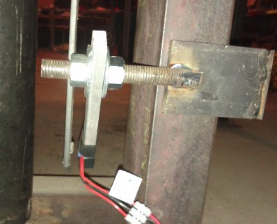
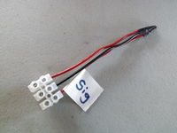
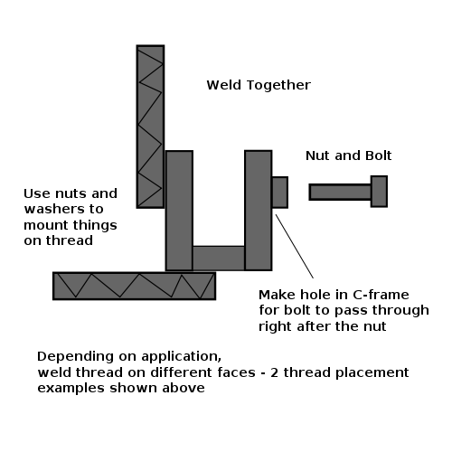
Installed on CEB Press. Adjustable for proximity to magnets, and up-down adjustable via clamp mechanism. Threaded rod is 3/4", and 2 bolts hold it firmly in place. Known bug: clamp mechanism around frame needs to use 2 - not 1 - bolts for clamping, otherwise rotation around bolt exists.
For CEB Press, weld thread parallel to bolt for one sensor and perpendicular to bolt for the second sensor.
Dimensions
Aluminum Rectangular Bar is 0.5" x 1.5" x
Materials
Aluminum and Steel - get them from SpeedyMetals
Aluminum Bar 6061T6 1/4" x 1/2" x 72"
Silicone Caulk Look for the "neutral cure" type of silicone caulk if using copper wires
22 AWG Stranded Wire of different colours
Cord jacket for 3 22AWG wires
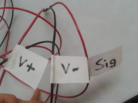
Wire Label (Important! Label your wires so you know which wire is connected to which pin- it'll save you a lot of trouble later on!)
Steps
- Cut 1 piece of aluminum flat bar to length (ex. 10cm)
- Cut 3 pieces of 22AWG wire and 1 piece of jacket to the desired length (ex. 150cm)
- Strip the 3 pieces of wire 10mm at one end and 20mm at the other end
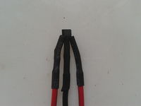
- Check and confirm which pins of the hall effect sensor are to which inputs/outputs (ex. V+, V-, Signal) see datasheet
- Solder the 20mm ends of the wires
- Solder and shrink tube the 10mm ends of the wires to the hall effect sensor pins
- Recheck which wires are connected to which pins
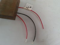
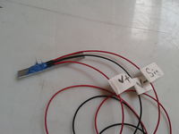
- Attach a label near the sensor to each wire about what the wire's pin is (ex. Red is V+, Black is V-, Green is Signal)
- Clamp or weigh down the wires near the sensor so that the sensor is stationary
- Position the aluminum flat bar underneath the sensor. The sensor should be near an end of the flat bar, the sensor's wire output parallel to the bar and inward toward the other end of the bar
- Apply silicone to the sensor and its pin-wire connection. The objective is to mount the sensor to the aluminum while waterproofing the pin-wire connection.
- Insert the 3 long wires into the jacket
Testing
Connect 5VDC power supply to + and - supply voltage wires for hall effect sensor. Measure voltage between signal wire and - supply wire using a multimeter. Wave a strong magnet over the hall effect sensor. Flip the magnet and wave it over the sensor again and repeat. The voltage reading should change each time you do this by approximately 1V.
